


33
Dirty Controller Test
The dirty controller test checks the controller’s ability to
initiate a dirty sensor test and indicate its results.
OPERATIONAL TEST ALERT
Failure to follow this ALERT can result in an
unnecessary evacuation of the facility.
Pressing the controller’s test/reset switch for longer
than seven seconds will put the duct detector into the
alarm state and activate all automatic alarm responses.
NOTICE
Dirty Controller Test Procedure
1. Press the controller’s test/reset switch for two
seconds.
2. Verify that the controller’s Trouble LED flashes.
Dirty Sensor Test
The dirty sensor test provides an indication of the sensor’s
ability to compensate for gradual environmental changes.
A sensor that can no longer compensate for environmental
changes is considered 100% dirty and requires cleaning or
replacing. You must use a field provided SD--MAG test
magnet to initiate a sensor dirty test. The sensor’s Dirty
LED indicates the results of the dirty test as shown in
Table 11.
OPERATIONAL TEST ALERT
Failure to follow this ALERT can result in an
unnecessary evacuation of the facility.
Holding the test magnet against the sensor housing for
more than seven seconds will put the duct detector
into the alarm state and activate all automatic alarm
responses.
NOTICE
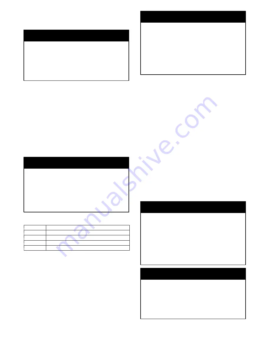
Table 11 – Dirty LED Test
FLASHES
DESCRIPTION
1
0---25% dirty. (Typical of a newly installed detector)
2
25---50% dirty
3
51---75% dirty
4
76---99% dirty
Dirty Sensor Test Procedure:
1. Hold the test magnet where indicated on the side of
the sensor housing for two seconds.
2. Verify that the sensor’s Dirty LED flashes.
OPERATIONAL TEST ALERT
Failure to follow this ALERT can result in an
unnecessary evacuation of the facility.
Changing the dirty sensor test operation will put the
detector into the alarm state and activate all automatic
alarm responses. Before changing dirty sensor test
operation, disconnect all auxiliary equipment from the
controller and notify the proper authorities if
connected to a fire alarm system.
NOTICE
Changing the Dirty Sensor Test
By default, sensor dirty test results are indicated by:
S
The sensor’s Dirty LED flashing.
S
The controller’s Trouble LED flashing.
S
The controller’s supervision relay contacts toggle.
The operation of a sensor’s dirty test can be changed so
that the controller’s supervision relay is not used to
indicate test results. When two detectors are connected to
a controller, sensor dirty test operation on both sensors
must be configured to operate in the same manner.
Configure the Dirty Sensor Test Operation:
1. Hold the test magnet where indicated on the side of
the sensor housing until the sensor’s Alarm LED turns
on and its Dirty LED flashes twice (approximately 60
seconds).
2. Reset the sensor by removing the test magnet then
holding it against the sensor housing again until the
sensor’s Alarm LED turns off (approximately 2
seconds).
Remote Station Test
The remote station alarm test checks a test/reset station’s
ability to initiate and indicate an alarm state.
OPERATIONAL TEST ALERT
Failure to follow this ALERT can result in an
unnecessary evacuation of the facility.
This test places the duct detector into the alarm state.
Unless part of the test, disconnect all auxiliary
equipment from the controller before performing the
test. If the duct detector is connected to a fire alarm
system,
notify
the
proper
authorities
before
performing the test.
NOTICE
OPERATIONAL TEST ALERT
Failure to follow this ALERT can result in an
unnecessary evacuation of the facility.
Holding the test magnet to the target area for longer
than seven seconds will put the detector into the alarm
state and activate all automatic alarm responses.
NOTICE
Summary of Contents for WeatherMaster 50HCQA04
Page 38: ...38 C10818 Fig 56 RTU OPEN Control Module ...
Page 78: ...78 APPENDIX V WIRING DIAGRAMS C150427 Fig 58 50HCQA04 A05 Control Wiring Diagram 575 3 60 ...
Page 80: ...80 APPENDIX V WIRING DIAGRAMS C160013 Fig 60 50HCQ 06 Control Wiring Diagram 575 3 60 ...
Page 84: ...84 APPENDIX V WIRING DIAGRAMS C150243 Fig 64 50HCQ 04 05 06 Power Wiring Diagram 208 230 1 60 ...
Page 85: ...85 APPENDIX V WIRING DIAGRAMS C12347 Fig 65 50HCQ 04 05 06 Power Wiring Diagram 208 230 3 60 ...
Page 86: ...86 APPENDIX V WIRING DIAGRAMS C12353 Fig 66 50HCQ 04 05 06 Power Wiring Diagram 460 3 60 ...
Page 87: ...87 APPENDIX V WIRING DIAGRAMS C12354 Fig 67 50HCQ 04 05 06 Power Wiring Diagram 575 3 60 ...
Page 91: ...91 APPENDIX V WIRING DIAGRAMS C12356 Fig 71 50HCQ 12 Power Wiring Diagram 460 3 60 575 3 60 ...
Page 92: ...92 APPENDIX V WIRING DIAGRAMS C150432 Fig 72 50HCQ PremierLink Control Diagram ...
Page 93: ...93 APPENDIX V WIRING DIAGRAMS C12359 Fig 73 50HCQ RTU Open Control Diagram ...