


21
Auxiliary (Electric) Heat Control
The 50HCQ unit can be equipped with one or two auxiliary elec-
tric heaters, to provide a second stage of heating. The DFB will
energize this Heating System for a Stage 2 Heating Command
(heaters operate concurrently with compressor(s) in the Stage 1
Heating cycle), for an Emergency Heating sequence (compressors
are off and only the electric heaters are energized) and also during
the Defrost cycle (to eliminate a “cold blow” condition in the
space).
Defrost
The defrost control mode is a time/temperature sequence. There
are two time components: The continuous run period and the test/
defrost cycle period. The temperature component is provided by
Defrost Thermostat 1 and 2 (DFT1 and DFT2) mounted on the
outdoor coil.
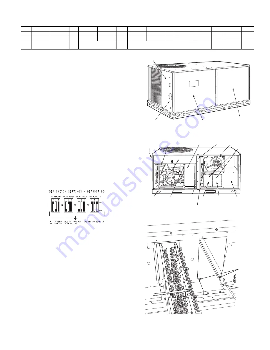
The continuous run period is a fixed time period between the end
of the last defrost cycle (or start of the current Heating cycle)
during which no defrost will be permitted. This period can be set
at 30, 60, 90, or 120 minutes by changing the positions of DIP
switches SW1 and SW2 (see Fig. 35 and Table 4). The default run
period is 30 minutes.
Shorting the jumpers for a period of 5 to 20 seconds bypasses the
remaining continuous run period and places the unit in a Forced
Defrost mode. If the controlling DFT is closed when this mode is
initiated, the unit will complete a normal defrost period that will
terminate when the controlling DFT opens or the 10 minute
defrost cycle limit is reached. If the controlling DFT is open when
this mode is initiated, the Defrost cycle will run for 30 seconds.
Both modes end at the end of the Defrost cycle.
Fig. 35 — DIP Switch Settings - Defrost Board
ELECTRIC HEATERS
50HCQ units may be equipped with field-installed accessory elec-
tric heaters. The heaters are modular in design, with heater frames
holding open coil resistance wires strung through ceramic insula-
tors, line-break limit switches and a control contactor. One or two
heater modules may be used in a unit.
Heater modules are installed in the compartment below the indoor
(supply) fan outlet. Access is through the indoor access panel.
Heater modules slide into the compartment on tracks along the
bottom of the heater opening. See Fig. 36-38.
Not all available heater modules may be used in every unit. Use
only those heater modules that are UL listed for use in a specific
size unit. Refer to the label on the unit cabinet for the list of ap-
proved heaters.
Unit heaters are marked with Heater Model Numbers, but heaters
are ordered as and shipped in cartons marked with a correspond-
ing heater Sales Package part number.
NOTE: The value in position 9 of the part number differs between
the sales package part number (value is 1) and a bare heater model
number (value is 0).
Fig. 36 — Typical Access Panel Location (3-6 Ton)
Fig. 37 — Typical Component Location
Fig. 38 — Typical Module Installation
Table 4 — DIP Switch Positions
1
2
1
2
1
2
1
2
3
1
1
1
1
1
On
0
0
0
0
0
Off
30 minutes
(factory default)
60 minutes
90 minutes
120 minutes
Fan Delay
DISCONNECT MOUNTING
LOCATION
UNIT BLOCK-OFF
PANEL
OUTDOOR
ACCESS PANEL
INDOOR
ACCESS
PANEL
DISCONNECT
MOUNTING
LOCATION
EMT OR RIGID CONDUIT
(FIELD-SUPPLIED)
SINGLE
POINT BOX
CENTER
POST
HEATER
COVERS
HEATER
MOUNTING
BRACKET
HEATER
MODULE
(LOCATION 2)
HEATER
MODULE
(LOCATION 1)
SINGLE POINT
BOX
MOUNTING
SCREW
BRACKET AND
CONDUIT
DRIP BOOT
MAIN
CONTROL
BOX
CONTROL WIRE TERMINAL BLOCK
MANUAL RESET
LIMIT SWITCH
TRACK
FLANGE
Summary of Contents for WeatherMaster 50HCQ 04 Series
Page 4: ...4 Fig 2 50HCQ 04 06 Units Built On and After 4 15 2019 ...
Page 5: ...5 Fig 3 50HCQ 04 06 Units Built Prior to 4 15 2019 ...
Page 6: ...6 Fig 4 50HCQ 04 06 Corner Weights and Clearances ...
Page 7: ...7 Fig 5 50HCQ 04 06 Base Rail Details ...
Page 8: ...8 Fig 6 50HCQ 04 06 Thru the Base Charts ...
Page 23: ...23 Fig 41 Electro Mechanical Control Wiring 208 230v 460v ...
Page 24: ...24 Fig 42 Electro Mechanical Control Wiring 575v ...
Page 25: ...25 Fig 43 Electro Mechanical Power Wiring 208 230 1 60 ...
Page 26: ...26 Fig 44 Electro Mechanical Power Wiring 208 230 3 60 ...
Page 27: ...27 Fig 45 Electro Mechanical Power Wiring 460 3 60 ...
Page 28: ...28 Fig 46 Electro Mechanical Power Wiring 575 3 60 ...
Page 29: ...29 Fig 47 PremierLink Wiring Schematic 208 230 460v ...
Page 30: ...30 Fig 48 PremierLink Wiring Schematic 575v ...