


4
GENERAL
This book contains Start-Up, Controls, Operation, Trouble-
shooting and Service information for the 48/50P Series rooftop
units. See Table 1. These units are equipped with
Comfort
Link
controls version 7.X or higher. Use this guide in conjunction
with the separate installation instructions packaged with the
unit. Refer to the Wiring Diagrams literature for more detailed
wiring information.
The 48/50P Series units provide ventilation, cooling, and
heating (when equipped) in variable air volume (VAV) and
constant volume (CV) applications.
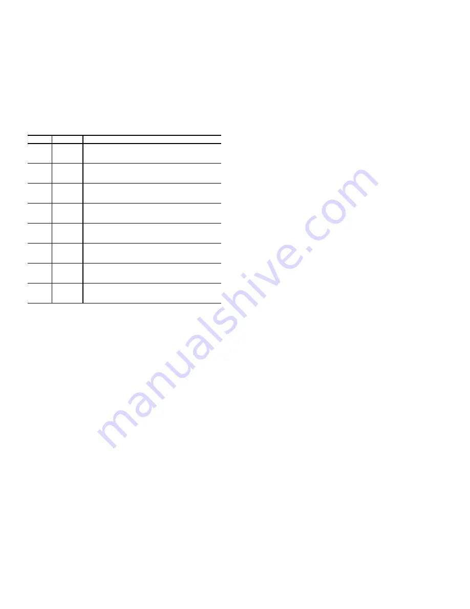
Table 1 — P Series Product Line
LEGEND
The 48/50P units contain the factory-installed
Comfort
Link
control system which provides full system management. The
main base board (MBB) stores hundreds of unit configuration
settings and 8 time of day schedules. The MBB also performs
self-diagnostic tests at unit start-up, monitors the operation of
the unit, and provides alarms and alert information. The system
also contains other optional boards that are connected to the
MBB through the Local Equipment Network (LEN). Informa-
tion on system operation and status is sent to the MBB proces-
sor by various sensors and the optional board located at the unit
and in the conditioned space. Access to the unit controls for
configuration, set point selection, schedule creation, and ser-
vice can be done through a unit-mounted scrolling marquee.
Access can also be done through the Carrier Comfort Net-
work
®
using ComfortVIEW™ software, Network Service
Tool, or the accessory Navigator™ device.
The
Comfort
Link system controls all aspects of the rooftop. It
controls the supply-fan motor, compressors, and economizers
to maintain the proper temperature conditions. The controls
also cycle condenser fans to maintain suitable head pressure.
All VAV units are equipped with a VFD (variable frequency
drive) for supply duct pressure control. The
Comfort
Link con-
trols can directly control the speed of the VFD based on a static
pressure sensor input. In addition, the
Comfort
Link controls
can adjust (but not control on CV and non-modulating power
exhaust units) the building pressure using multiple power ex-
haust fans controlled from damper position or from a building
pressure sensor. The control safeties are continuously moni-
tored to prevent the unit from operating under abnormal condi-
tions. Sensors include pressure transducers and thermistors.
A scheduling function, programmed by the user, controls the
unit occupied/unoccupied schedule. Up to 8 different schedules
can be programmed.
The controls also allow the service person to operate a service
test so that all the controlled components can be checked for
proper operation.
Conventions Used in This Manual
This manual will use the following conventions for discussing
configuration points for the local display (scrolling marquee or
Navigator™ accessory).
Parameter names will be written with the Mode name first,
then any submodes, then the parameter name, each separated
by an arrow symbol (
). Names will also be shown in bold
and italics. As an example, the IAQ Economizer Override Po-
sition which is located in the Configuration mode, Indoor Air
Quality Configuration sub-mode, and the Air Quality Set
Points sub-sub-mode, would be written as
Configuration
IAQ
IAQ.SP
IQ.O.P
.
This path name will show the user how to navigate through the
local display structure to reach the desired configuration. The
user would scroll through the modes and submodes using the
UP ARROW and DOWN ARROW keys. The arrow symbol in
the path name represents pressing ENTER to move into the
next level of the menu structure.
When a value is included as part of the path name, it will be
shown at the end of the path name after an equals sign. If the
value represents a configuration setting, an explanation will be
shown in parentheses after the value. As an example,
Configu-
ration
IAQ
AQ.CF
IQ.A.C
= 1 (IAQ Analog Input).
Pressing the ESCAPE and ENTER keys simultaneously will
scroll an expanded text description of the parameter name
across the display. The expanded description is shown in the
local display tables but will not be shown with the path names
in text.
The CCN (Carrier Comfort Network
®
) point names are also cross-
referenced in the local display tables (Appendix A) for users con-
figuring the unit with CCN software instead of the local display.
The CCN tables are located in Appendix B of this manual.
BASIC CONTROL USAGE
Comfort
Link Controls
The
Comfort
Link controls are a comprehensive unit-management
system. The control system is easy to access, configure, diagnose
and troubleshoot.
The controls are flexible, providing constant volume and vari-
able air volume cooling control sequences, and heating control
sequences for two-stage electric and gas systems, multiple-
stage gas heating, and hydronic heat in both Occupied and Un-
occupied schedule modes. This control also manages:
• VAV duct pressure (through optional VFD), with configu-
rable static pressure reset
• Building pressure through four different power exhaust
schemes
• Return fan applications using fan tracking
• Condenser fan head pressure control
• Dehumidification (with optional reheat) and humidifier
sequences
• Space ventilation control, in Occupied and Unoccupied pe-
riods, using CO
2
sensors or external signals, with ventila-
tion defined by damper position or ventilation airflow
measurement
• Smoke control functions
• Occupancy schedules
UNIT
SIZE
APPLICATION
48P2
All
Gas Heat
Vertical Supply/Return
CV ComfortLink Controls
48P3
All
Gas Heat
Vertical Supply/Return
VAV ComfortLink Controls
48P4
All
Gas Heat
Horizontal Supply/Return
CV ComfortLink Controls
48P5
All
Gas Heat
Horizontal Supply/Return
VAV ComfortLink Controls
50P2
All
Optional Electric Heat
Vertical Supply/Return
CV ComfortLink Controls
50P3
All
Optional Electric Heat
Vertical Supply/Return
VAV ComfortLink Controls
50P4
All
Optional Electric Heat
Horizontal Supply/Return
CV ComfortLink Controls
50P5
All
Optional Electric Heat
Horizontal Supply/Return
VAV ComfortLink Controls
CV
—
Constant Volume
VAV —
Variable Air Volume
Summary of Contents for Weathermaster 48P2030-100
Page 130: ...130 Fig 19 Typical Power Schematic Sizes 040 075 Shown ...
Page 131: ...131 Fig 20 Main Base Board Input Output Connections ...
Page 132: ...132 Fig 21 RXB EXB CEM SCB Input Output Connections ...
Page 133: ...133 Fig 22 Typical Gas Heat Unit Control Wiring 48P030 100 Units Shown ...
Page 134: ...134 Fig 23 Typical Electric Heat Wiring 50P030 100 Units Shown ...
Page 135: ...135 Fig 24 Typical Power Wiring 115 V ...
Page 136: ...136 Fig 25 Typical Gas Heat Section Size 030 050 Units Shown ...
Page 138: ...138 Fig 27 Component Arrangement Size 030 035 Units ...
Page 139: ...139 Fig 28 Component Arrangement Size 040 075 Units ...
Page 140: ...140 Fig 29 Component Arrangement Size 090 100 Units ...