67
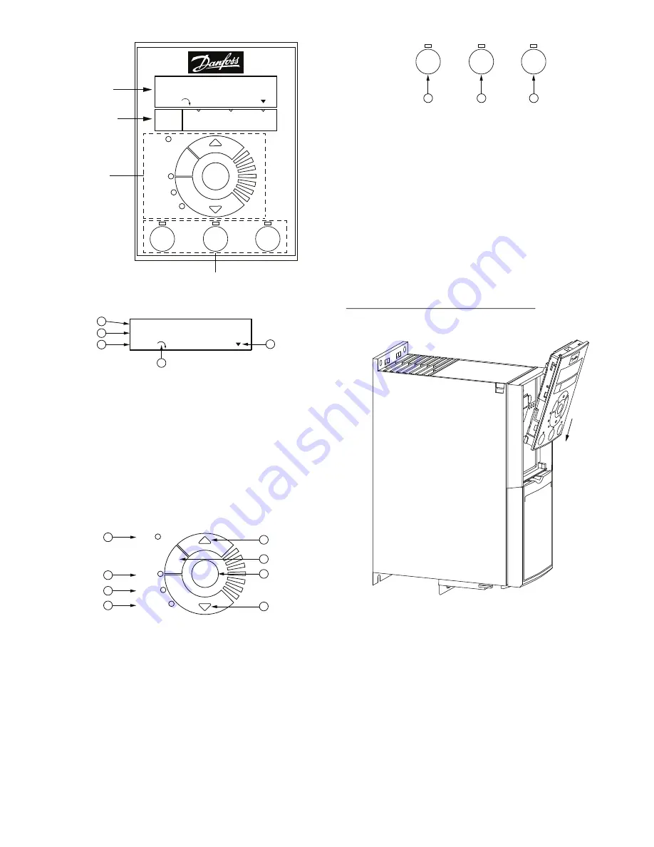
Fig. 80 —
VFD Keypad
Fig. 81 —
Alphanumeric Display
Fig. 82 —
Navigation Keys and Status LEDs
Fig. 83 —
Operation Keys and LEDs
Connecting the Keypad to the VFD
The VFD keypad can be mounted directly to the variable frequen
-
cy drive, provided you can easily access the front panel of the
VFD. If you do not have easy access to the VFD front panel, use
the cable included with the kit to connect the keypad to the VFD.
Connecting the Keypad Directly to the VFD
1. Place the bottom of the VFD keypad into the variable fre
-
quency drive as shown in Fig. 84.
Fig. 84 —
Aligning Bottom of VFD Keypad with
Opening in VFD Front Panel
2. Push the top of the VFD keypad into the variable fre
-
quency drive as shown in Fig. 85.
1
= Parameter number and name.
2
= Parameter value.
3
= Setup number shows the active setup and the edit setup. If
the same setup acts as both the active and edit setup, only
that setup number is shown (factory setting). When the
active and edit setup differ, both numbers are shown in the
display (SETUP 12). The flashing number indicates the edit
setup.
4
= The symbol in the number 4 position in the figure above indi-
cates motor direction. The arrow points either clockwise or
counter-clockwise to show the motor’s current direction.
5
= The position of the triangle indicates the currently selected
menu: Status, Quick Menu or Main Menu.
1
= Com. LED: Flashes when bus communications is
communicating.
2
= Green LED/On: Control selection is working.
3
= Yellow LED/Warn.: Indicates a warning.
4
= Flashing Red LED/Alarm: Indicates an alarm.
5
= Arrows: Use the Up and Down arrow keys to navigate
between parameter groups, parameters and within parame-
ters. Also used for setting local reference.
6
= Back key: Press to move to the previous step or
layer in the navigation structure.
7
= OK key: Press to select the currently displayed
parameter and for accepting changes to parameter
settings.
Off
Reset
Hand
On
Alarm
Warn.
On
Com.
OK
Ba
ck
Auto
On
Status
Menu
Quick
Menu
Main
Menu
1-20 Motor Power
[2] 0.12KW-0.16HP
Setup 1
ALPHA
NUMERIC
DISPLAY
MENU KEY
NAVIGATION
KEYS
AND
STATUS
LEDs
OPERATION KEYS & LEDs
1-20 Motor Power
[2] 0.12KW-0.16HP
Setup 1
1
3
2
4
5
Alarm
Warn.
On
Com.
OK
Ba
ck
3
4
1
2
5
6
5
7
1
= Hand On key: Starts the motor and enables control of the
variable frequency drive (VFD) via the VFD Keypad option.
NOTE: Please note that terminal 27 Digital Input (5-12 Ter-
minal 27 Digital Input) has coast inverse as default setting.
This means that the Hand On key will not start the motor if
there is no 24V to terminal 27, so be sure to connect terminal
12 to terminal 27.
2
= Off/Reset key: Stops the motor (off). If in alarm mode the
alarm will be reset.
3
= Auto On key: The variable frequency drive is controlled either
via control terminals or serial communication.
Off
Reset
Hand
On
Auto
On
1
2
3
Summary of Contents for WeatherExpert 50LC14
Page 4: ...4 Fig 2 50LC Vertical Airflow Size 14...
Page 5: ...5 Fig 3 50LC Horizontal Airflow Size 14...
Page 6: ...6 Fig 4 50LC Back View and Condensate Drain Location Size 14...
Page 7: ...7 Fig 5 50LC Corner Weights and Clearances Size 14...
Page 8: ...8 Fig 6 50LC Bottom View Size 14...
Page 9: ...9 Fig 7 50LC Vertical Airflow Sizes 17 20...
Page 10: ...10 Fig 8 50LC Horizontal Airflow Sizes 17 20...
Page 11: ...11 Fig 9 50LC Back View and Condensate Drain Location Sizes 17 20...
Page 12: ...12 Fig 10 50LC Corner Weights and Clearances Sizes 17 20...
Page 13: ...13 Fig 11 50LC Bottom View Sizes 17 20...
Page 14: ...14 Fig 12 50LC Vertical Airflow Sizes 24 26...
Page 15: ...15 Fig 13 50LC Horizontal Airflow Sizes 24 26...
Page 16: ...16 Fig 14 50LC Back View and Condensate Drain Location Sizes 24 26...
Page 17: ...17 Fig 15 50LC Corner Weights and Clearances Sizes 24 26...
Page 18: ...18 Fig 16 50LC Bottom View Sizes 24 26...
Page 21: ...21 Fig 19 Roof Curb Details 14 Size Unit...
Page 22: ...22 Fig 20 Roof Curb Details 17 and 20 Size Units...
Page 23: ...23 Fig 21 Roof Curb Details 24 and 26 Size Units...
Page 30: ...30 Fig 42 50LC 14 26 Electro Mechanical Control Wiring Diagram...
Page 31: ...31 Fig 43 50LC 14 26 RTU Open Control Wiring Diagram...
Page 32: ...32 Fig 44 50LC 14 26 SystemVu Control Wiring Diagram...
Page 35: ...35 Fig 47 Typical Power Wiring Diagram SystemVu Controls 50LC Unit 208 230V Shown...
Page 36: ...36 Fig 48 Typical Power Wiring Diagram SystemVu Controls 50LC Unit 460V 575V Shown...
Page 80: ......
Page 81: ......


