


50
VAV Cool Mode Selection during the Unoccupied Period
(C.TYP = 1,2; Operating Modes
MODE
OCC=OFF) and
Space Sensor Cool Mode Selection (C.TYP=4)
The machine control types that utilize this technique of mode
selection are:
•
C.TYP
= 1 (VAV-RAT) in the unoccupied period
•
C.TYP
= 2 (VAV-SPT) in the unoccupied period
•
C.TYP
= 4 (SPT-MULTI) in both the occupied and unoc
-
cupied period
These particular control types operate differently than the VAV
types in the occupied mode in that there is both a LOW COOL
and a HIGH COOL mode. For both of these modes, the control
offers 2 independent set points,
Setpoints
SA.LO
(for LOW
COOL mode) and
Setpoints
SA.HI
(for HIGH COOL mode).
The occupied and unoccupied cooling set points can be found
under
Setpoints
.
The heat/cool set point offsets are found under
Configura
-
tion
BP
D.LV.T
.
Operating modes are under
Operating Modes
MODE
.
Cool Mode Evaluation Logic
The first thing the control determines is whether the unit is in the
occupied mode (
OCC
) or is in the temperature compensated start
mode (
T.C.ST
). If the unit is occupied or in temperature compen
-
sated start mode, the occupied cooling set point (
OCSP
) is used.
For all other modes, the unoccupied cooling set point (
UCSP
) is
used. For further discussion and simplification, this will be re
-
ferred to as the “cooling set point.” See Fig. 5.
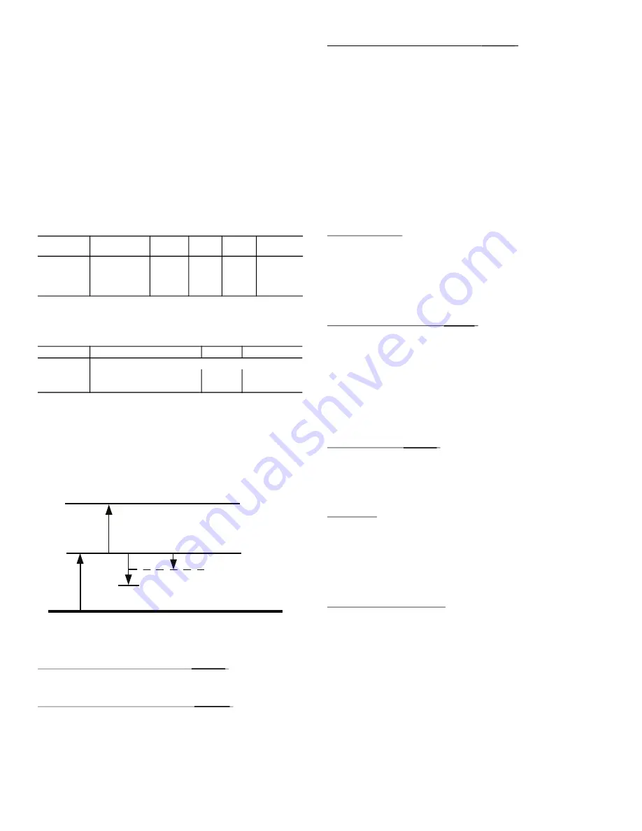
Fig. 5 —
Cool Mode Evaluation
Demand Level Low Cool On Offset
(
L.C.ON
)
This is the cooling set point offset added to the cooling set
point at which point a Low Cool mode starts.
Demand Level High Cool On Offset
(
H.C.ON
)
This is the cooling set point offset added to the “cooling set
point plus
L.C.ON
” at which point a High Cool mode begins.
Demand Level Low Cool Off Offset
(
L.C.OF
)
This is the cooling set point offset subtracted from “cooling set
point plus
L.C.ON
” at which point a Low Cool mode ends.
NOTE: The “high cool end” trip point uses the “low cool off”
(
L.C.OF
) offset divided by 2.
To enter into a LOW COOL mode, the controlling temperature
must rise above [the cooling set point plus
L.C.ON
.]
To enter into a HIGH COOL mode, the controlling temperature
must rise above [the cooling set point plus
L.C.ON
plus
H.C.ON
.]
To exit out of a LOW COOL mode, the controlling temperature
must fall below [the cooling set point plus
L.C.ON
minus
L.C.OF
.
]
To exit out of a HIGH COOL mode, the controlling tempera
-
ture must fall below [the cooling set point plus
L.C.ON
minus
L.C.OF
/2.]
Comfort Trending
In addition to the set points and offsets which determine the
trip points for bringing on and bringing off cool modes, there
are 2 configurations which work to hold off the transitioning
from a low cool to a high cool mode if the space is cooling
down quickly enough. This technique is referred to as comfort
trending, and the configurations of interest are
C.T.LV
and
C.T.TM
.
Cool Trend Demand Level
(
C.T.LV
)
This is the change in demand that must occur within the time
period specified by
C.T.TM
in order to hold off a HIGH COOL
mode, regardless of demand. This is not applicable to VAV
control types (
C.TYP
=1 and 2) in the occupied period. As long
as a LOW COOL mode is making progress in cooling the
space, the control will hold off on the HIGH COOL mode. This
is especially true for the space sensor machine control type
(
C.TYP
) = 4 because the unit may transition into the occupied
mode and see an immediate large cooling demand when the set
points change.
Cool Trend Time
(
C.T.TM
)
This is the time period upon which the cool trend demand level
(
C.T.LV
) operates and may hold off staging or a HIGH COOL
mode. This is not applicable to VAV control types (
C.TYP
=1
and 2) in the occupied period. See the Cool Trend Demand
Level section for more details.
Timeguards
In addition to the set points and offsets that determine the trip
points for bringing on and bringing off cool modes, there is a
timeguard that enforces a time delay between the transitioning
from a low cool to a high cool mode. This time delay is 8 min
-
utes. There is a timeguard which enforces a time delay between
the transitioning from a heat mode to a cool mode. This time
delay is 5 minutes.
Supply Air Set Point Control
Once the control has determined that a cooling mode is in effect,
the cooling control point (
Run Status
VIEW
CL.C.P
) is cal
-
culated and is based upon either
Setpoints
SA.HI
or
Set
-
points
SA.LO
, depending on whether a high or a low cooling
mode is in effect, respectively. In addition, if supply air reset is
configured, it will also be added to the cooling control point.
Refer to the SumZ Cooling Algorithm section for a discussion of
how the N Series
Comfort
Link controls manage supply-air tem
-
perature and the staging of compressors for these control types.
ITEM
EXPANSION RANGE UNITS
CCN
POINT DEFAULT
OCSP
Occupied
Cool Setpoint 55-80
dF
OCSP 75
UCSP
Unoccupied
Cool Setpoint 75-95
dF
UCSP 90
ITEM
EXPANSION
RANGE
CCN POINT
MODE
MODES CONTROLLING UNIT
OCC
Currently Occupied
Off/On
MODEOCCP
T.C.ST
Temp.Compensated Start
Off/On
MODETCST
H.C.ON
L.C. OF/2
L.C.ON
Cooling
S
etpoint (OC
S
P,UC
S
P)
L.C. OF
Lo Cool End
Hi Cool End
Lo Cool
S
t
a
rt
Hi Cool
S
t
a
rt
Summary of Contents for WeatherExpert 48N2
Page 135: ...135 Fig 18 48 50N Typical Power Schematic Nominal 075 Ton Unit Shown ...
Page 136: ...136 Fig 19 48 50N Typical Power Schematic Nominal Ton 90 150 Units Shown ...
Page 137: ...137 Fig 20 48 50N Main Base Board Input Output Connections ...
Page 138: ...138 Fig 21 48 50N RXB EXB CEM Input Output Connections a48 9307 ...
Page 139: ...139 Fig 22 48 50N EXV SCB Input Output Connections a48 9308 ...
Page 140: ...140 Fig 23 48N Typical Modulating Gas Heat Unit Control Wiring ...
Page 141: ...141 Fig 24 50N Typical Electric Heat Unit Control Wiring ...
Page 144: ...144 Fig 27 48N Typical Gas Heat Section Wiring Nominal Ton 120 to 150 Units ...
Page 145: ...145 Fig 28 48 50N Typical Power Component Control Wiring 460 v ...
Page 146: ...146 Fig 29 48 50N Component Control Wiring 575 v Nominal Ton 075 to 150 Units ...
Page 147: ...147 Fig 30 48 50N Component Arrangement Power Box ...
Page 148: ...148 Fig 31 48 50N Component Arrangement Control Box ...
Page 240: ...240 APPENDIX D VFD INFORMATION CONT Fig G VFD Bypass Wiring Diagram WHEN USED ...