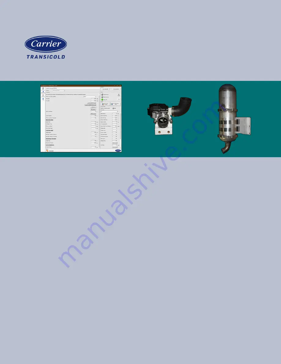
Container Refrigeration
OPERATIONS AND SERVICE
MANUAL
For
Engine Emission System (EES)
UG15 Tier 4 Generator Sets
T-378
Page 1: ...Container Refrigeration OPERATIONS AND SERVICE MANUAL For Engine Emission System EES UG15 Tier 4 Generator Sets T 378...
Page 2: ...OPERATIONS AND SERVICE MANUAL For Engine Emission System EES UG15 Tier 4 Generator Sets Carrier Corporation 2021 Printed in U S A September 2021...
Page 3: ...YSTEM EES OVERVIEW 3 1 3 2 EXHAUST SYSTEM DESCRIPTION 3 2 3 2 1 Diesel Oxidation Catalyst DOC 3 2 3 2 2 Diesel Particulate Filter DPF 3 2 3 3 FUEL INJECTOR DOSER DESCRIPTION 3 3 3 3 1 Fuel Injector Do...
Page 4: ...HE EES SERVICE TOOL 5 4 5 4 OPERATION WITH 250 HOUR SERVICE MODE ALARM ACTIVE 5 4 SERVICE 6 1 6 1 ENGINE MAINTENANCE 6 1 6 2 EES MAINTENANCE 6 1 6 3 SERVICE DIAGNOSTICS 6 1 6 4 DPF MANUAL CLEANING 6 1...
Page 5: ...4 1 ECM Service Tool 4 1 Figure 4 2 ECM CAN Adapter 4 1 Figure 4 3 ECM Service Tool Connected 4 2 Figure 4 4 ECM Service Tool Component Check 4 3 Figure 4 5 ECM Service Tool Manual Regeneration 4 4 Fi...
Page 6: ...e 8 1 Retrofit Kit 74 00324 00 for EES Field Installation 8 1 Table 8 2 Exhaust Kit 76 00955 00 8 1 Table 8 3 Air Control Valve ACV Kit 76 00956 00 8 2 Table 8 4 Coolant Kit 76 00957 00 8 2 Table 8 5...
Page 7: ...arries an explanation is given with the appropriate consequences DANGER DANGER means an immediate hazard that WILL result in severe personal injury or death WARNING WARNING means to warn against a haz...
Page 8: ...to install and maintain the Engine Emission System EES All required procedures must be adhered to and all documentation must be properly filed Proper operation must be confirmed at the time of instal...
Page 9: ...of your diesel emission control strategy Failure to document proper engine maintenance including oil consumption records may be grounds for denial of a warranty claim for a failed component of a diese...
Page 10: ......
Page 11: ...ons as the muffler when installed and reduces the exhaust related noise emitted from the unit The process of burning off the particulate matter in the EES is called Regeneration This is where temperat...
Page 12: ...er in a filter but allows exhaust gas to pass through The DPF uses a Wall Flow Filter WFF design which allows exhaust gases to pass through micro porous walls Particles of diesel soot and other debris...
Page 13: ...es on the surface of the DOC to raise the exhaust temperature and oxidize the particulate matter in the DPF Automatic regeneration is initiated by the Emissions Control Module ECM Refer to Section 3 7...
Page 14: ...Control Valve ACV 3 5 Emissions Control Module ECM Description The Emissions Control Module ECM Figure 3 7 monitors the EES parameters using an internal back pressure sensor along with temperature se...
Page 15: ...ring high engine load passive regeneration will occur Refer to Section 3 7 for a description of how regeneration works Figure 3 9 ESEIT 3 6 2 Filter Inlet Temperature Sensor ESFIT The Filter Inlet Tem...
Page 16: ...F a process called regeneration is utilized During regeneration the temperature in the DPF is increased to a level that oxidizes the captured soot leaving only fine inorganic ash and significantly red...
Page 17: ...l ratio and increases the exhaust temperature entering the DOC Once the exhaust temperature reaches the level required for Active Regeneration the Doser injects fuel into the upstream pipe After regen...
Page 18: ......
Page 19: ...n display alarm codes provide current sensor readings retrieve data from the ECM and more The ECM Service Tool software v2 0 28 is required to communicate with the ECM This can be downloaded from the...
Page 20: ...re 4 3 ECM Service Tool Connected 4 2 Component Check Component check Figure 4 4 is for testing the functionality of individual EES components by cycling the components on and off Each component will...
Page 21: ...the injector 4 2 3 Fuel Pump 1 From the Setup Screen click on the AR DOC tab 2 Click the DO6 Fuel pump button once to activate the fuel pump As the fuel pump cycles the pump motor will make a slight...
Page 22: ...2 Start the unit and allow the unit to run for 15 minutes to warm up the DPF 3 Click the Jump TO REGENERATION mode button to initiate regeneration The system will automatically start a complete regene...
Page 23: ...cted the EES Service Light will go from Amber to Green and the timer will be reset Refer to Figure 4 6 Refer to Section 5 1 for a list of alarms and troubleshooting information 1 From the Setup Screen...
Page 24: ...red Alarm conditions where the EES becomes inoper able will initiate a 250 hour timer After 250 hours the unit will shut down until the system is repaired by a qualified technician Refer to Figure 4...
Page 25: ...alarm text turns green and the System Indicator turns green Refer to Figure 4 9 Figure 4 9 ECM Service Tool Alarms Cleared 4 5 Sensor Readings The ECM Service Tool can display current readings for the...
Page 26: ...ownload may be necessary for troubleshooting the EES Refer to Figure 4 11 1 From the Retrieve Data screen click on the Retrieve data button The Receiving log data dialog box will be displayed 2 Once t...
Page 27: ...ware tab 2 Click on the Update ECM with firmware button A window will prompt to locate the new software file 3 Choose the new software file and click Open A window will open showing progress of the do...
Page 28: ......
Page 29: ...d manual mode Activate a manual regeneration Refer to Section 4 3 Check for other alarms in queue and inspect the EES 3 Low Back Pressure The back pressure has been less than 4 in H2O 1 kPa for more t...
Page 30: ...ration Refer to Section 4 3 Repair components as required 34 Check Fuel Pump Circuit Fuel Pump Current Draw is outside the acceptable range of 500 mA 8 0 Amps when energized Check fuel pump operation...
Page 31: ...cate a leak in the system Replace if necessary 45 Exhaust Inlet Temp Exhaust Inlet Temperature is less than 100 C or more than 1100 C at any time Inspect the Exhaust Inlet Temperature Sensor ESEIT Ref...
Page 32: ...the 250 hour window of continued operation has started and the timer is currently counting down When the 250 hours is over the generator set will shut down During this period automatic regeneration in...
Page 33: ...ovide current sensor readings retrieve data from the ECM and more Further diagnosis with the ECM requires the following tools ECM CAN Adapter 07 00533 01 ECM Service Tool software version 2 0 28 Detai...
Page 34: ...gine mode and initiate a regeneration Check back pressure readings on the ECM Service Tool Refer to Section 4 5 If back pressure reading is higher than 120 in H2O 30 kPa then the filter may require ad...
Page 35: ...7 1 T 378 SECTION 7 SCHEMATICS Figure 7 1 Schematic...
Page 36: ......
Page 37: ...y Includes 1 1a 86 05115 00 Bracket Assembly 1 1b 30 00510 04 Diesel Particulate Filter DPF Assembly Includes 1 30 00510 51 DPF 1 30 00510 57 Outlet 1 30 00510 63 DPF Gasket 2 30 00510 64 Diesel Oxida...
Page 38: ...rew Cap Hxhd 2 1h 34 00655 14 Screw Cap Hxhd 1 1i 34 00663 11 Washer Lock 3 1j 12 00736 00 ACV Throttle 1 2 86 05099 01 Bracket Weld 1 3 34 00807 10 Screw Cap Hxhd 4 4 34 00663 13 Washer Lock 4 5 66 U...
Page 39: ...17 6 68 17691 00 Angle Mounting 1 7 68 17692 00 Angle Mounting 1 8 34 00807 10 Screw Cap Hxhd 2 9 66 U 1 5321 17 Washer Plain 2 10 34 00663 13 Washer Lock 2 11 22 04331 00 Clip Push On 4 Table 8 6 Fu...
Page 40: ...Hxhd 6 16 68 17743 00 Bracket Mtg 1 17 58 00849 22 Tube Slit 1 18 68 18485 00 Angle Bracket 1 19 34 00655 06 Screw Cap Hxhd 1 20 34 00663 11 Washer Lock 1 21 68 17742 00 Angle Bracket 1 22 58 01503 0...
Page 41: ...ve 2000 14 EC following Annex III The following Harmonized Standards were applied for this equipment The following Technical Standard was applied for this equipment ISO 1496 2 2018 Person established...
Page 42: ......
Page 43: ...ist Regeneration 3 4 3 7 Active Regeneration 3 7 Air Control Valve ACV Description 3 4 Air Control Valve ACV Location 3 1 Air Control Valve ACV Manual Activation 4 2 Ash Handling Guidelines 6 1 Automa...
Page 44: ...ser Valve 3 3 Fuel Injector Doser Manual Activation 4 3 Fuel Pump Manual Activation 4 3 G General Safety Notices 1 1 H Higher Exhaust Temperatures 3 6 I Inorganic Ash 3 1 3 6 Introduction 2 1 K KA 69J...
Page 45: ...micals known to the State of California to cause cancer and birth defects or other reproductive harm Always start and operate the engine in a well ventilated area If in an enclosed area vent the exhau...