


62-11637
8–46
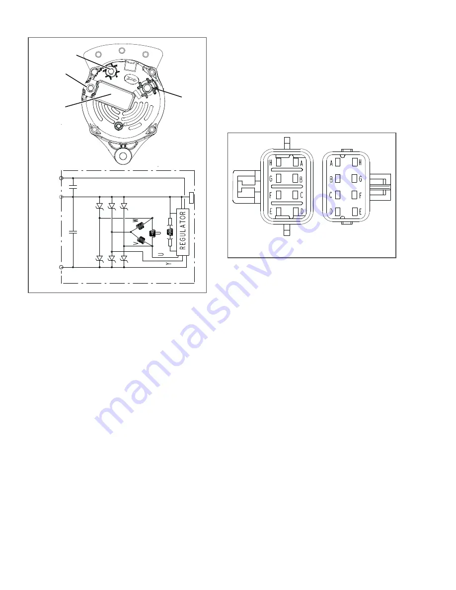
Figure 8.42 Alternator
1. Positive Output Terminal (B+)
2. L (D+) Terminal
3. Ground Terminal (B-)
4. Regulator/Brush Assembly
- - - - -
a. Inspection
1. Ensure the unit will not start automatically by
disabling any two way communication, placing
the STOP/RUN-OFF switch in the OFF position
and removing the negative battery cable.
2. Verify condition and tightness of connections
(see
). Torque B+ terminal 62 to 80
inch/lbs (7 to 9 Nm) and B- terminal 38 to 52
inch/lbs (4.3 to 5.9 Nm). Check condition of belt,
refer to
.
b. Brush Replacement
1. Ensure the unit will not start automatically by
disabling any two way communication, placing
the STOP/RUN-OFF switch in the OFF position
and removing the negative battery cable.
2. Remove the screws holding the regulator/brush
assembly.
3. Replace with new regulator/brush assembly.
Torque mounting screws 35 to 40 inch/lbs (4 to
4.5 Nm).
4. Start unit and run Pretrip to check operation.
c. Alternator Replacement
In the event the alternator is replaced, install the pulley
on the alternator shaft with the “shoulder” side toward
the alternator. Torque left hand thread pulley nut 50 to
60 ft/lbs (68 to 88 Nm) while holding shaft using a six
point Torx T50 wrench. For instruction on tightening
alternator mounting hardware and checking belt, refer
to
Figure 8.43 Light Bar Connections
8.10.6
Light Bar
The light bar may be tested using a 12 VDC source. To
test the light bar:
1. Connect the ground (-) from the power source to
pin G on the light bar side of the connector.
2. The green LED’s will illuminate when the 12
VDC side (+) of the power source is connected
to pin B.
3. With the connection as in the preceding steps (+
on pin B, and - on pin G), the amber LED’s will
illuminate when the power (+) from the power
source is also connected to pin H.
4. Start unit and run Pretrip to check operation.
8.10.7
Sensor Checkout
An accurate ohmmeter must be used to check resis-
.
Due to variations and inaccuracies in ohmmeters, ther-
mometers or other test equipment, a reading within 2%
of the chart value would indicate a good sensor. If a
sensor is bad, the resistance reading will usually be
much higher or lower than the resistance values given
in the tables.
Two preferred methods of determining the actual test
temperature at the sensor, is an ice bath at 32°F (0°C)
or a calibrated temperature tester.
%
%
‐
/
'
A
H
E
F
G
D
C
B
LIGHT BAR
SIDE
CONTROL BOX
SIDE
A
H
E
F
G
D
C
B
Summary of Contents for Transicold X4 7300
Page 21: ...62 11637 1 6 1 3 SAFETY DECALS ...
Page 22: ...1 7 62 11637 62 03958 ...
Page 23: ...62 11637 1 8 ...
Page 24: ...1 9 62 11637 ...
Page 119: ...62 11637 SECTION 6 MESSAGECENTER PARAGRAPH NUMBER Page 6 1 MESSAGECENTER MESSAGES 6 1 ...
Page 278: ......