


8–33
62-11637
3. Break any remaining vacuum (raise to 0 psig/
bar) with refrigerant remaining in the system
(crack open the suction service valve), or from a
fresh cylinder of refrigerant. Evacuate the com-
pressor crankcase to 500 microns. Remove ser-
vice equipment, backseat suction and discharge
service valves and recheck oil level.
c. Removing Oil From The Compressor
1. Check compressor oil level, refer to preceding
step a. If the oil level is above the maximum
mark on the crankcase, oil must be removed
from the compressor.
2. Pump down the compressor. Refer to
.
3. Ensure the unit will not start automatically by dis-
abling any two way communication and placing
the STOP/RUN-OFF switch in the OFF position.
4. Loosen the oil drain plug (item 10,
and allow oil to seep out and bring the level to 1/
8 glass. Tighten the plug securely back into the
compressor.
5. Leak check the oil drain plug, refer to
. Start compressor and recheck oil level.
8.8.6
Unloaders
a. Unloader Checkout Procedure
1. Install a manifold gauge set on the compressor
suction and discharge service valves and start
unit in cooling with compartment temperature at
least 5°F (2.8°C) above setpoint. The compres-
sor will be fully loaded (both unloader coils de-
energized). Note suction pressure.
2. Unplug both unloader coils.
3. Using a 12 VDC source, energize the front
unloader (UL1). Note discharge and suction
pressures. A rise of approximately 3 psig (0.2
bar) will be noted on the suction pressure
gauge. Discharge pressure should drop approxi-
mately 5 to 15 psig (0.4 to 1.0 bar).
4. De
−
energize UL1 and note pressures. Suction
pressure should drop and discharge pressure
should rise by same amount as in step 3 above.
5. Repeat steps 3 & 4 for the rear unloader (UL2).
At the end of the test, reconnect both unloaders.
NOTE
If pressures do not change as indicated,
check the unloader coil resistance (refer to
). Replace if coil is open or
shorted. If either unloader coil energizes and
the suction and discharge pressures do not
change, the unloader assembly must be
checked.
b. Unloader Coil Replacement
NOTE
The coil may be removed while the compres-
sor is under pressure.
1. Disconnect leads and lift coil (see
off enclosing tube.
2. Verify replacement coil is the correct type, volt-
age and frequency.
3. Place new coil over enclosing tube. With wiring
facing in the desired direction, ensure roll pin is
fitted in one of the detents in the bottom of the
coil mounting. Coll is to snap into place with bot-
tom in contact with the enclosing tube nut. Con-
nect wiring.
4. Check operation, refer to preceding step a.
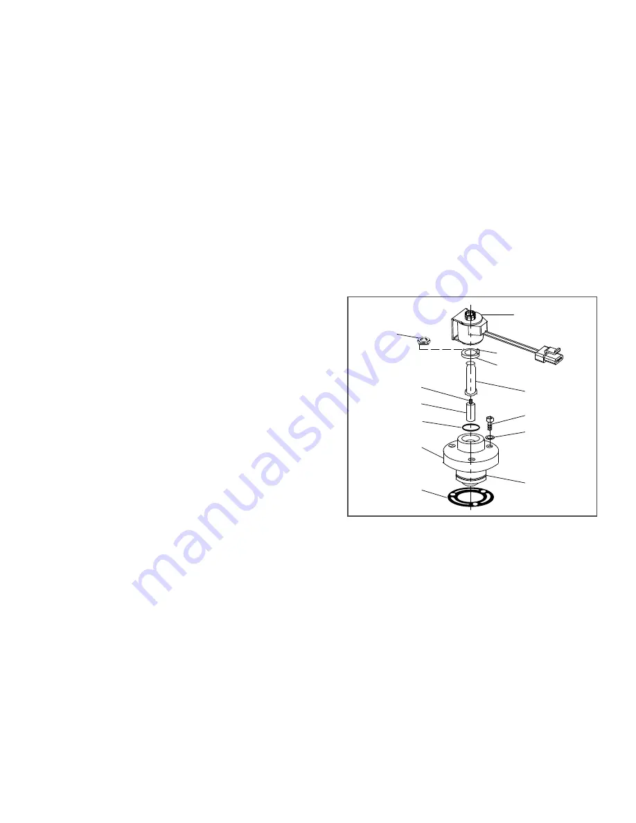
Figure 8.29 Unloader Coil
c. Replacing Unloader Valve Internal Parts
1. Pump down the compressor. Refer to
.
2. Ensure the unit will not start automatically by dis-
abling any two way communication and placing
the STOP/RUN-OFF switch in the OFF position.
3. Disconnect and remove coil.
1. Coil Assembly
2. Pin, Roll
3. Enclosing Tube Nut
4. Enclosing Tube
5. Bolts, Valve Body (3)
6. Washers (3)
7. Piston
8. Gasket
9. Valve Body
10. “O” Ring
11. Plunger
12. Plunger Spring
13. Installation/Removal
Tool
- - - - -
Summary of Contents for Transicold X4 7300
Page 21: ...62 11637 1 6 1 3 SAFETY DECALS ...
Page 22: ...1 7 62 11637 62 03958 ...
Page 23: ...62 11637 1 8 ...
Page 24: ...1 9 62 11637 ...
Page 119: ...62 11637 SECTION 6 MESSAGECENTER PARAGRAPH NUMBER Page 6 1 MESSAGECENTER MESSAGES 6 1 ...
Page 278: ......


