


62-11637
5–14
5.4.3
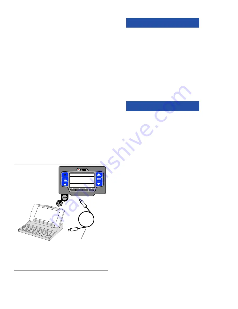
Connecting Computer and Control System
To connect the control system and computer:
1. Locate the USB interface port (item 18,
) and remove the protective cover to gain
access.
2. Plug a PC–USB service cable into the port and
a USB port on the computer (see
).
NOTE
If Configured to do so, the System will
prompt for entry of the data protect PIN code
(refer to “PROTECT DATA WITH PIN”,
The System will power up, and display “PC
MODE”.
3. Start the TRU-Tech & TRU-View program by
double clicking on the icon on your computer
desktop and entering the required password.
Verify that the correct COM port is selected in
the PC Setup. For complete instructions on
using TRU-Tech & TRU-View, refer to the man-
ual supplied with the TRU
−
Tech/TRU
−
View
software.
4. When work is complete, remove the interface
cable and install the protective cover back onto
the USB port. The control system will return to
normal operation.
Figure 5.11 TRU-Tech/TRU-View Connection
5.5
MAIN MICROPROCESSOR REPLACEMENT
NOTICE
Under no circumstances should a techni-
cian electrically probe the modules at any
point, other than the connector terminals
where the harness attaches. Module com-
ponents operate at different voltage levels
and at extremely low current levels.
Improper use of voltmeters, jumper wires,
continuity testers, etc. could permanently
damage the module.
Some main microprocessor inputs operate at voltage
levels other than the conventional 12 VDC. These inputs
include but are not limited to the pressure transducers
and temperature sensors. Under no circumstances
should 12 VDC be applied at these connection points.
NOTICE
Electronic modules MUST be handled
with care to prevent accidental damage
or degradation from electrical static dis-
charge (ESD), contamination or abuse.
Before touching a module, touch your
body and/or conductive tool being used
to the frame to discharge ESD safely. All
electronics should be handled carefully
and only held by edges of any exposed
board. Care should be taken when insert-
ing/extracting connectors and compo-
nents to avoid exerting excessive stress
on the board which could fracture small
components nearby, resulting in future
failure of circuit.
When field diagnosis of a Carrier Transicold refrigeration
unit determines that an APX main microprocessor is not
performing properly and must be replaced the replace-
ment microprocessor must be setup for this unit and
customer by entering the required Configurations, Func-
tional Parameters and DataLink data recorder settings.
If the replacement microprocessor is not loaded with
the most recent software, it should be updated. If soft-
ware is loaded, it should be verified that it is the
approved revision for this model.
The preferred method for setup of the main micropro-
cessor is to use the display mounted keys or a Data
Transfer USB memory device. All required changes,
except unit specific and time sensitive data, may be
performed using the device. If a USB is not available
the main microprocessor may be setup using TRU-
Tech. TRU-Tech allows entry of all required data. If
neither a USB memory device or TRU-Tech and ser-
vice cable is available, the main microprocessor may
be setup for immediate use using the display mounted
keys. Changes to the default DataLink data recorder
settings may not be entered using the display mounted
PC–USB Service Cable. Carrier Transicold
Part #: 22–04253–01 = 20 foot/6.1 meter long)
NOTE: Only this cable will communicate
correctly. An “off the shelf” USB to USB cable
will not provide the required communication.
PRESS = TO LOAD, OTHER TO EXIT
SOFTWARE INSTALL MENU
CURRENT SOFTWARE VERSION:
##.##.01
SOFTWARE ON USB: ##.##.02
Summary of Contents for Transicold X4 7300
Page 21: ...62 11637 1 6 1 3 SAFETY DECALS ...
Page 22: ...1 7 62 11637 62 03958 ...
Page 23: ...62 11637 1 8 ...
Page 24: ...1 9 62 11637 ...
Page 119: ...62 11637 SECTION 6 MESSAGECENTER PARAGRAPH NUMBER Page 6 1 MESSAGECENTER MESSAGES 6 1 ...
Page 278: ......