


62-11637
5–12
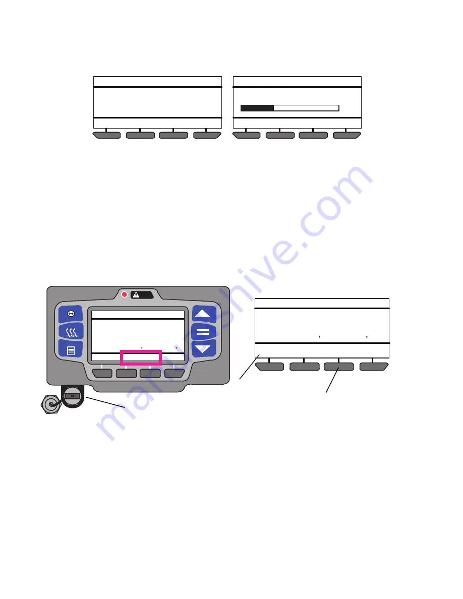
6. Once the “=” key is pressed, the operator message panel will display “UNIT AND MICRO WILL STOP
NOW” and the unit will stop. The System will begin downloading software from the USB memory device and
the operator message panel will display “SOFTWARE INSTALL IN PROGRESS”. The percent downloaded
will display as the software is copied and then the operator message panel will display “SOFTWARE
INSTALL COMPLETE - MICRO WILL RESTART NOW - REMOVE USB.
7. After install is complete, reinstall the USB, press the INSTALL SOFTWARE soft key and then the “=” key to
verify the software matches that on the USB.
5.3.5
Transferring Configuration Files
Instructions for installing configuration files into the control system from a Data Transfer USB memory device are
provided in
. Configuration” (*.set) files consist of one of the following types of files. A “Configuration”
file contains a complete set of Configuration, Functional Parameter and Data Recorder settings for the system. An
“IntelliSet” file contains multiple Configurations which are programmed using easily recognizable names that can
then be selected using the display mounted keys by the operator. A “Maintenance” file contains one or more indi-
vidual settings. For example: Remote Sensor Yes/No, Fuel Level Sensor: Yes/No. etc. Unit specific and time sen-
sitive data cannot be loaded to a configuration file. This data includes: model number, serial number, trailer ID hour
meter readings, date and time. These configurations must be set using the display mounted keys or TRU-Tech and
a service cable.
Figure 5.10 Transferring Configuration Files
1. Ensure the desired setting file(s) are loaded to the “CONFIG” folder on a Data Transfer USB memory
device.
2. With the System powered or off, remove protective cover from the USB interface port and Insert the device.
The MessageCenter will display READING USB. NOTE: If configured to do so, the System will prompt for
entry of the data protect PIN code (refer to “PROTECT DATA WITH PIN”,
3. The Message Center will then display the USB soft keys. (NOTE: The INSTALL SOFTWARE soft key will
not display if a file is not loaded In the PROGRAM folder.)
4. Press the INSTALL SETTINGS soft key. The System will enter the INSTALL SETTINGS menu.
5. If one or more configuration file(s) are loaded on the Data Transfer USB memory device a listing of available
files will be displayed. To scroll through the files press the
▲
or
▼
key. The files will highlight as the list is
scrolled.
NOTE
Earlier software versions may have a display maximum of 10 files. If the desired file does not display,
reduce the USB CONFIG directory content to 10 or less.
DO NOT REMOVE USB
SOFTWARE INSTALL MENU
UNIT AND MICRO WILL STOP NOW
SOFTWARE INSTALL MENU
SOFTWARE INSTALL IN PROCESS
33%
DO NOT REMOVE USB
CONTINUOUS
START/STOP
MENU
ALARM
DEFROST
COOL
DIESEL
START/STOP
READING USB
36
36
.2
BOX TEMPERATURE F
SETPOINT F
DOWNLOAD
DATA
INSTALL
SOFTWARE
COOL
DIESEL
START/STOP
36
36
.2
BOX TEMPERATURE F
SETPOINT F
INSTALL
SETTINGS
2
3
4
Summary of Contents for Transicold X4 7300
Page 21: ...62 11637 1 6 1 3 SAFETY DECALS ...
Page 22: ...1 7 62 11637 62 03958 ...
Page 23: ...62 11637 1 8 ...
Page 24: ...1 9 62 11637 ...
Page 119: ...62 11637 SECTION 6 MESSAGECENTER PARAGRAPH NUMBER Page 6 1 MESSAGECENTER MESSAGES 6 1 ...
Page 278: ......


