


10
4
– SMARTVU USER INTERFACE
4.1 - Touch screen display
SmartVu is a 4.3 in. colour touch screen with quick display of
alarms, current unit operating status, etc. It allows for web
connectivity and custom language support (control parameters
displayed in the language selected by the user).
▪
If the touch screen is not used for a while, the screen
will go black. The control system is always active and
the operating mode remains unchanged. Press
anywhere on the screen and the Home screen will be
displayed.
▪
It is recommended to use a stylus for the navigation via
the touch screen.
4.2 - Home screen (synoptic view)
The home screen is the starting point of the controller. It is also
the first screen shown after starting the user interface.
Please note that the picture of the rooftop is for illustration only and it may differ from
the actual look of the chiller that is available on field. The image displayed on the
home screen represents the whole series of 48UC(V) / 50UC(V).
Legend:
1. Header buttons and subheader buttons
2. Equipment view
3. Information message box (see section 4.4)
The home screen allows you to monitor basic information about
the operation of the chiller and its working conditions.
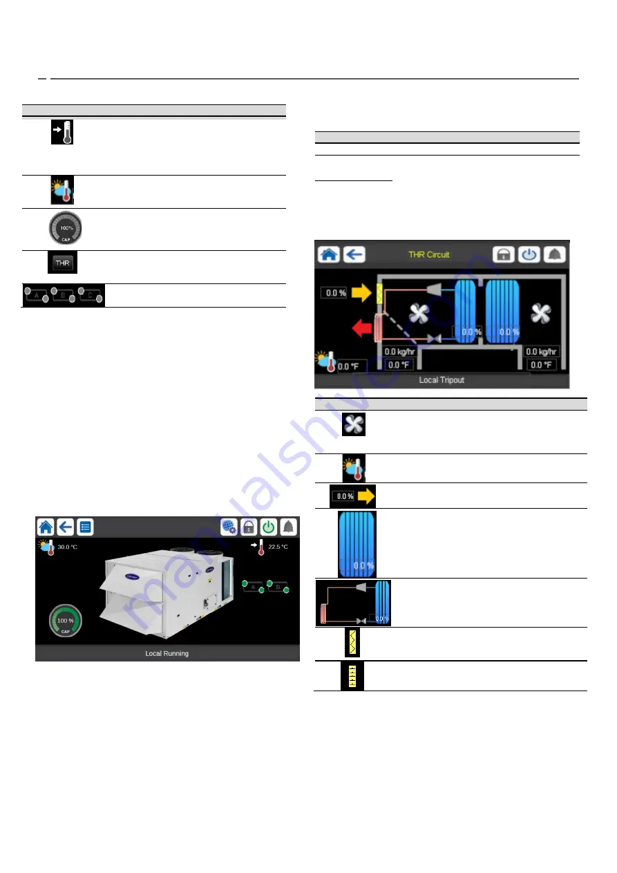
4.3
– THR page
THR page is only available if THR circuit is configured.
Icon
Description
Fan:
the image is animated when the fan is running.
The fan on the right is the supply fan and the values
below are the current supply airflow and SAT. The fan
on the left is return fan and the values below are return
airflow and RAT.
Outdoor Air Temperature (OAT):
This parameter
is displayed only in case of units fitted with OAT
sensor.
Current freshair supply fan
RTU
: It shows the total unit capacity. The image will
be in blue if the capacity is > 0 and in grey otherwise.
Circuit THR:
It shows the circuit THR capacity. The
image will be in blue if the capacity is > 0 and in grey
otherwise.
Economizer damper:
This image will appear if
economizer position is equal to 0.
Economizer damper:
This image will appear if
economizer position is higher than 0.
4.4 - Information message box
The information displayed in the status bar at the bottom of the
screen includes relevant messages related to actions taken by the
user.
Icon
Description
Setpoint:
This parameter is used to
display the currently selected setpoint.
Press the icon to modify the setpoint
(possible only when logged in!, see section
5.8).
Outdoor Air Temperature (OAT):
This
parameter is displayed only in case of
units fitted with OAT sensor.
Unit capacity:
The gauge shows current
unit capacity.
Thermodynamic Energy Recovery (THR):
Will
be printed if THR is configured. By clicking on
this button, the THR page will appear (See
section 4.3)
Circuits A, B and C
: Will be printed depending
on the configured circuits
MESSAGE
STATUS
SUCCESS
Displayed when the requested action is executed.
INTERNAL
COMMUNICATION
FAILURE!
Displayed when the main application is not running.
HIGH FORCE IN
EFFECT!
Displayed when the controller rejects the “Force”
command (applicable only to status menus).
ACCESS DENIED!
Displayed when trying to perform actions not
allowed at current access level.


