background image

38

For best results wash coils from discharge side and wash back to-

ward the fan or unit return filters. Clean coils with a vacuum

cleaner, fresh water, compressed air, or a bristle brush (not wire).

Backflush coil to remove debris. Commercial coil cleaners may

also be used to help remove grease and dirt. Steam cleaning is

NOT recommended. Units installed in corrosive environments

should be cleaned as part of a planned maintenance schedule. In

this type of application, all accumulations of dirt should be

cleaned off the coil.
Use a fin comb with teeth of the correct fin spacing when straight-

ening bent or mashed fins.
During heating operation, the vacuum-return system is recom-

mended since it helps eliminate any residual condensate from the

coil.
The steam distribution coils have a significantly reduced possibili-

ty of freeze-ups. They are still susceptible to freezing, however, if

a minimum steam quantity is not maintained where air over the

coil approaches 32°F, or if they are not properly pitched, drained,

trapped and controlled.
The following points should also be considered for freeze protec-

tion of steam distributing coils.
In cases where outside air is admitted to the unit, it should be suffi-

ciently mixed with return air before reaching the coil in order to

avoid cold spots on the coil. It is important that a minimum steam

quantity be maintained when heat is called for to prevent water re-

maining in the tubes and possibly freezing. The ON-OFF type of

steam control is preferred over modulating control where air tem-

perature over the coil approaches 32°F. Make sure that closed out-

side air dampers are sufficiently sealed to prevent air leakage. Low

leak style dampers are recommended.
Make sure that the coil is properly pitched, drained, and trapped so

that condensate drains out of the coil whenever the control valve

shuts off the steam supply.

Checking System Charge

The 50XCW units are shipped with full operating charge. If re-

charging is necessary:
1. Insert thermometer bulb in insulating rubber sleeve on liquid

line near filter drier. Use a digital thermometer for all tem-

perature measurements. DO NOT use a mercury or dial-type

thermometer.

2. Connect refrigerant pressure gage to discharge line near

compressor.

3. After unit condition have stabilized, read head pressure on

discharge line gage.

NOTE: Operate unit a minimum of 15 minutes before check-

ing charge.

4. From standard pressure-temperature chart for R-410A, find

equivalent saturated condensing temperature.

5. Read liquid line temperature on thermometer; then subtract

from saturated condensing temperature. The difference

equals subcooling temperature.

6. Compare the subcooling temperature with the normal tem-

perature listed in Table 13. If the measured liquid line tem-

perature does not agree with the required liquid line

temperature, ADD refrigerant to raise the temperature or
REMOVE refrigerant (using standard practices) to lower the

temperature (allow a tolerance of ± 3°F).
Example:
Head pressure (from gage) 416.4 psig
Saturated condensing temp (from chart) 120°F
Liquid line temp (from thermometer) 100°F
Subcooling (by subtraction) 20°F

*Saturated condensing temperature at compressor minus liquid line
temperature.

NOTE: Do not vent or depressurize unit refrigerant to atmosphere.

Remove and recover refrigerant following accepted practices.

Access Panel Removal

TOP PANEL
Remove 3 to 6 screws, pull out panel and remove.
CONTROL PANEL
Remove 4 screws and remove panel.
BOTTOM PANEL
Remove 3 to 6 screws in bottom panel and lift up to remove panel.

Evaporator-Fan Motor Removal

NOTE: Motor power wires need to be disconnected from control

box terminals before motor is removed from unit.
1. Shut off unit main power supply. Lock out power supply and

tag disconnect locations.

2. Loosen bolts on mounting bracket so that fan belt can be

removed.

3. Disconnect motor power wires from motor terminals.
4. Remove the 4 motor mounting bolts from bottom of motor.
5. Remove motor. Rest motor securely on a high platform such

as a step ladder. Do not allow motor to hang by its power

wires.

Pressure Relief Device

All units are equipped with a fusible-plug type safety relief device

on the refrigerant tubing. The relief setting is 210°F.

Current Protection Device 

All units are equipped with a current-sensing lockout relay on

each circuit. This device will lock out the compressor after any

safety trip (high-pressure switch, low-pressure switch, or internal

overload of the compressor) for 5 minutes. Check reason for lock-

out before resetting the device. To reset, turn the thermostat sys-

tem switch to OFF, then back to COOL position.

High and Low-Pressure Switches 

The high-pressure switch is located on the compressor discharge

line. The low-pressure switch is located on the suction line.

Oil Charge

All units are factory charged with oil (see Table 1 for compressor

model number). It is not necessary to add oil unless the compres-

sor is removed from the unit. If additional oil is needed, do not use

mineral oils. Only synthetic oils are satisfactory.

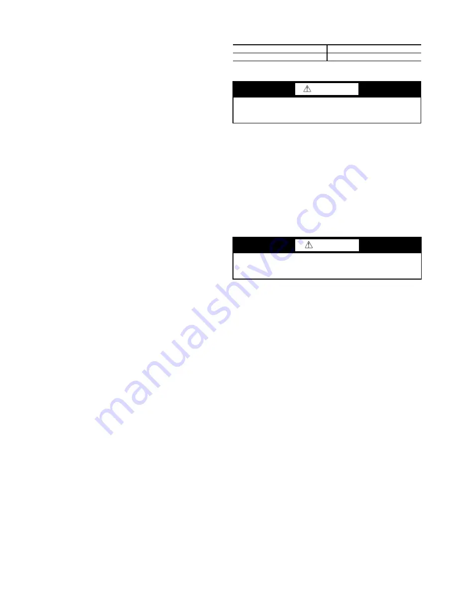
Table 13 — Subcooling Temperature

UNIT 50XCW

SUBCOOLING*

06-24

12°F

WARNING

To prevent personal injury, wear safety glasses and gloves

when handling refrigerant. Do not overcharge system — this

can cause compressor flooding.

CAUTION

Before attempting to remove fan motors or motor mounts,

place a piece of plywood over evaporator coils to prevent coil

damage.

Summary of Contents for Omnizone 50XCW06

Page 1: ... 1 SAFETY CONSIDERATIONS Installing starting up and servicing air conditioning components and equipment can be dangerous Only trained qualified installers and service mechanics should install start up and service this equipment When working on the equipment observe precautions in the liter ature and on tags stickers and labels attached to the equipment Follow all safety codes Wear safety glasses a...

Page 2: ...n instructions before installing the unit Step 1 Complete Pre Installation Checks Examine unit for damage incurred during shipment File claim im mediately with transit company if damage is found Check the shipment for completeness Verify that the nameplate electrical re quirements match the available power supply DO NOT place the unit in a horizontal position that would allow oil to drain into the...

Page 3: ...R RETURN CONN WATER SUPPLY CONN EVAP SUPPLY DUCT Blower Opening SUPPLY RETURN DIAMETER OD A B C D E F G H I J K L M N O P Q R 06 53 1 57 0 29 0 25 8 31 0 47 2 24 8 28 9 4 8 14 4 23 0 22 9 7 5 13 4 12 8 2 7 19 8 1 625 08 53 1 57 0 29 0 25 8 31 0 47 2 24 8 28 9 4 8 14 4 23 0 22 9 7 5 13 4 12 8 2 7 7 6 1 625 NOTE Dimensions are in inches SIZE SIZE ...

Page 4: ...ECTION EVAPORATOR RETURN DUCT WATER RETURN CONN WATER SUPPLY CONN EVAP SUPPLY DUCT Blower Opening SUPPLY RETURN DIAMETER OD A B C D E F G H I J K L M N O P Q R 12 68 0 64 0 31 2 28 0 35 5 61 1 31 8 29 4 5 5 17 7 22 7 10 8 4 2 12 5 13 8 8 5 13 6 2 125 14 68 0 64 0 31 2 28 0 35 5 61 1 31 8 29 4 5 5 17 7 22 7 10 8 4 2 12 5 13 8 8 5 13 6 2 125 ...

Page 5: ...ECTION EVAP SECTION EVAPORATOR RETURN DUCT WATER RETURN CONN WATER SUPPLY CONN EVAP SUPPLY DUCT Blower Opening SUPPLY RETURN DIAMETER OD A B C D E F G H I J K L M N O P Q R 12 68 0 64 0 31 2 28 0 35 5 61 1 31 8 29 4 5 5 17 7 22 7 25 6 10 1 12 5 13 8 8 5 13 6 2 125 14 68 0 64 0 31 2 28 0 35 5 61 1 31 8 29 4 5 5 17 7 22 7 25 6 10 1 12 5 13 8 8 5 13 6 2 125 ...

Page 6: ...12 68 0 64 0 31 2 28 0 35 5 61 1 31 8 29 4 5 5 17 7 22 7 23 9 8 1 12 5 13 8 8 5 13 6 2 125 14 68 0 64 0 31 2 28 0 35 5 61 1 31 8 29 4 5 5 17 7 22 7 23 9 8 1 12 5 13 8 8 5 13 6 2 125 a50 8847 5 1 1 2 FLTR 6 8 4 FLTR E D B K M J L 6 8 2 5 R R 1 3 3 4 MPT DRAIN 9 5 1 25 POWER ENTRY 1 25 CONTROL ENTRY C AIR FLOW FILTER ACCESS BOTH SIDES WATER RETURN WATER SUPPLY A F I G H 5 4 P O N N Q Q DISCONNECT OP...

Page 7: ...SECTION EVAPORATOR RETURN DUCT WATER RETURN CONN WATER SUPPLY CONN EVAP SUPPLY DUCT Blower Opening SUPPLY RETURN DIAMETER OD A B C D E F G H I J K L M N O P Q R 12 68 0 64 0 31 2 28 0 35 5 61 1 31 8 29 4 5 5 17 7 22 7 10 8 4 2 12 5 13 8 2 7 13 6 2 125 14 68 0 64 0 31 2 28 0 35 5 61 1 31 8 29 4 5 5 17 7 22 7 10 8 4 2 12 5 13 8 2 7 13 6 2 125 ...

Page 8: ...SECTION EVAP SECTION EVAPORATOR RETURN DUCT WATER RETURN CONN WATER SUPPLY CONN EVAP SUPPLY DUCT Blower Opening SUPPLY RETURN DIAMETER OD A B C D E F G H I J K L M N O P Q R 12 68 0 64 0 31 2 28 0 35 5 61 1 31 8 29 4 5 5 17 7 22 7 25 6 10 1 12 5 13 8 2 7 13 6 2 125 14 68 0 64 0 31 2 28 0 35 5 61 1 31 8 29 4 5 5 17 7 22 7 25 6 10 1 12 5 13 8 2 7 13 6 2 125 ...

Page 9: ...O P Q R 12 68 0 64 0 31 2 28 0 35 5 61 1 31 8 29 4 5 5 17 7 22 7 23 9 8 1 12 5 13 8 2 7 13 6 2 625 14 68 0 64 0 31 2 28 0 35 5 61 1 31 8 29 4 5 5 17 7 22 7 23 9 8 1 12 5 13 8 2 7 13 6 2 625 5 1 1 2 FLTR 6 8 4 FLTR E D B K M 1 2 J L 2 5 6 8 R R 3 4 MPT DRAIN 9 5 1 25 POWER ENTRY 1 25 CONTROL ENTRY C WATER SUPPLY WATER RETURN EVAP ACCESS PANEL BOTH SIDES AIR FLOW FILTER ACCESS N N Q Q P O DISCONNECT...

Page 10: ...N EVAPORATOR RETURN DUCT WATER RETURN CONN WATER SUPPLY CONN EVAP SUPPLY DUCT Blower Opening SUPPLY RETURN DIAMETER OD A B C D E F G H I J K L M N O P Q S R 16 88 0 66 7 31 2 31 2 35 5 81 0 31 8 33 2 5 5 17 8 22 8 10 7 4 2 12 5 13 8 8 5 13 5 11 7 2 625 24 88 0 70 8 31 2 31 2 39 5 81 5 35 8 33 3 5 5 17 8 22 8 10 7 4 2 14 9 13 8 8 6 8 3 13 2 2 625 ...

Page 11: ...N EVAP SECTION EVAPORATOR RETURN DUCT WATER RETURN CONN WATER SUPPLY CONN EVAP SUPPLY DUCT Blower Opening SUPPLY RETURN DIAMETER OD A B C D E F G H I J K L M N O P Q S R 16 88 0 66 7 31 2 31 2 35 5 81 0 31 8 33 2 5 5 17 8 22 8 25 6 10 1 12 5 13 8 8 5 13 5 11 7 2 625 24 88 0 70 8 31 2 31 2 39 5 81 5 35 8 33 3 5 5 17 8 22 8 25 6 10 1 14 9 13 8 8 6 8 3 13 2 2 625 ...

Page 12: ...CTION EVAPORATOR RETURN DUCT WATER RETURN CONN WATER SUPPLY CONN EVAP SUPPLY DUCT Blower Opening SUPPLY RETURN DIAMETER OD A B C D E F G H I J K L M N O P Q S R 16 88 0 66 7 31 2 31 2 35 5 81 0 31 8 33 2 5 5 17 8 22 8 24 0 8 9 12 5 13 8 8 5 13 5 11 7 2 625 24 88 0 70 8 31 2 31 2 39 5 81 5 35 8 33 3 5 5 17 8 22 8 24 0 8 9 14 9 13 8 8 6 8 3 13 2 2 625 a50 8673 ...

Page 13: ...ION EVAPORATOR RETURN DUCT WATER RETURN CONN WATER SUPPLY CONN EVAP SUPPLY DUCT Blower Opening SUPPLY RETURN DIAMETER OD A B C D E F G H I J K L M N O P Q S R 16 88 0 66 7 31 2 31 2 35 5 81 0 31 8 33 2 5 5 17 8 22 8 10 7 4 2 12 5 13 8 2 6 13 5 11 7 2 625 24 88 0 70 8 31 2 31 2 39 5 81 5 35 8 33 3 5 5 17 8 22 8 10 7 4 2 14 9 13 8 2 6 8 3 13 2 2 625 ...

Page 14: ...ON EVAPORATOR RETURN DUCT WATER RETURN CONN WATER SUPPLY CONN EVAP SUPPLY DUCT Blower Opening SUPPLY RETURN DIAMETER OD A B C D E F G H I J K L M N O P Q S R 16 88 0 66 7 31 2 31 2 35 5 81 0 31 8 33 2 5 5 17 8 22 8 25 6 10 1 12 5 13 8 2 6 13 5 11 7 2 625 24 88 0 70 8 31 2 31 2 39 5 81 5 35 8 33 3 5 5 17 8 22 8 25 6 10 1 14 9 13 8 2 6 8 3 13 2 2 625 WATER RETURN WATER SUPPLY ...

Page 15: ... R 16 88 0 66 7 31 2 31 2 35 5 81 0 31 8 33 2 5 5 17 8 22 8 24 0 8 9 12 5 13 8 2 6 13 5 11 7 2 625 24 88 0 70 8 31 2 31 2 39 5 81 5 35 8 33 3 5 5 17 8 22 8 24 0 8 9 14 9 13 8 2 6 8 3 13 2 2 625 R R 5 1 1 2 FLTR 6 8 4 FLTR E D 1 2 K B M J L 3 0 7 0 9 5 1 25 POWER ENTRY 1 25 CONTROL ENTRY C 3 4 MPT DRAIN WATER RETURN WATER SUPPLY FILTER ACCESS AIR FLOW EVAP ACCESS PANEL BOTH SIDES P Q Q N N N S O DI...

Page 16: ...tor Pulley Type 1VL44 1VP34 1VP34 1VP34 1VP34 1VP50 Std Hp 1 0 1 0 1 0 1 5 1 5 3 Hp Range 1 2 1 2 1 3 1 5 5 1 5 5 3 7 5 Fan Shaft Size in 0 75 1 1 1 1 1875 1 1875 Motor Shaft Size in 0 875 0 875 0 875 0 875 0 875 1 125 Center Distance in Vertical 15 3 15 3 18 1 18 1 18 1 21 3 Center Distance in Horizontal N A N A 15 5 13 15 7 18 1 EVAPORATOR COIL 3 8 in OD Enhanced Copper Tube Aluminum Fins Quanti...

Page 17: ... The fac tory filter should be left in place on a free return system If the unit will be installed in a new installation the duct system should be designed in accordance with the System Design Manu al Part 2 and with ASHRAE procedures for duct sizing If the unit will be connected to an existing duct system check that the exist ing duct system has the capacity to handle the required airflow for the...

Page 18: ...lectrical Connections GENERAL Verify that nameplate electrical requirements match available power supply Voltage at condenser must be within the minimum and maximum shown in Tables 2 and 3 and phases must be bal anced within 2 Contact local power company for line voltage corrections Never operate a motor where a phase imbalance in supply voltage is greater than 2 UNBALANCED 3 PHASE SUPPLY VOLTAGE ...

Page 19: ... FREEZE PROTECTION THERMOSTAT A standard freeze protection thermostat is factory installed LEGEND NOTES 1 In compliance with NEC requirements for multimotor and combina tion load equipment NEC Articles 430 and 440 the overcurrent protective device for the unit shall be fuse or HACR circuit breaker Canadian units may be fuse or circuit breaker 2 Wire sizing amps are a sum of 125 of the compressor R...

Page 20: ... 253 3 2 3 2 460 3 60 414 506 1 6 575 3 60 518 632 1 1 E 1 50 208 230 3 60 187 253 4 6 4 8 460 3 60 414 506 2 4 575 3 60 518 632 1 6 F 2 00 208 230 3 60 187 253 6 0 5 8 460 3 60 414 506 2 9 575 3 60 518 632 2 1 G 3 00 208 230 3 60 187 253 9 2 8 6 460 3 60 414 506 4 3 575 3 60 518 632 3 4 H 5 00 208 230 3 60 187 253 14 5 13 6 460 3 60 414 506 6 8 575 3 60 518 632 5 4 J 7 50 208 230 3 60 187 253 21 ...

Page 21: ...ent cold spots on the coil that could freeze 7 Two position control valves modulating control valves or three way control valves may be used to control water flow Select the valve based on the control valve manufacturer s recommendations for size and temperature rating Select the control valve based on pressure drop equal to the coil 8 Pipe sizes should be selected based on the head pressure avail...

Page 22: ...ater COMP Compressor CLO Compressor Lockout DISC Disconnect FRZ Freeze Protection GND Ground HPS High Pressure Switch HR Heater Relay IFC Indoor Fan Contactor IFM Indoor Fan Motor IFR Indoor Fan Relay LLT Low Limit Thermostat LPS Low Pressure Switch OFC Outdoor Fan Contactor OFM Outdoor Fan Motor OFR Outdoor Fan Relay SAT Supply Air Thermistor TB Terminal Block TRAN Transformer Terminal Block Conn...

Page 23: ...t traps Ther mostatic traps should only be used for air venting Bucket traps are recommended for use with ON OFF control 7 Locate the trap at least 12 in below the coil return 8 If a modulating control valve is used be sure to size the valve properly and do not oversize Fig 21 Typical Steam Distributing Coil Piping for Open Gravity Systems with Steam Pressure Below 10 psig Fig 22 Typical Steam Dis...

Page 24: ...ut driver secure plenum mounting angles to 50XCW unit using 3 no 10 5 8 in long screws provided with plenum Install 3 screws along each plenum side and 5 screws along plenum front and rear mounting angles 4 Adjust four way deflection vanes as needed to ensure ade quate airflow distribution LEGEND C Compressor Contactor CH Crankcase Heater COMP Compressor CLO Compressor Lockout DISC Disconnect FRZ ...

Page 25: ...tretch Check the belt tension after 24 hours of operation and adjust if necessary Periodically check belt tension throughout the run in period which is normally the initial 72 hours of operation Fig 25 Determining Sheave Shaft Overhang ALIGNMENT Make sure that fan shafts and motor shafts are parallel and level The most common causes of misalignment are nonparallel shafts and improperly located she...

Page 26: ...ete set of new belts Mixing old and new belts will result in the premature wear or breakage of the newer belts Refer to label on inside of fan access door for information on fac tory supplied drive 1 Always adjust the motor position so that V belts can be installed without stretching over grooves Forcing belts can result in uneven stretching and a mismatched set of belts 2 Do not allow belt to bot...

Page 27: ... below room temperature Com pressor will start If compressor suction pressure does not drop and discharge pressure does not rise to normal levels at start up reverse any 2 compressor power leads and restore power to ensure compressor was not wired to run in reverse direction 6 Set thermostat as desired Compressor Rotation To determine whether or not compressor is rotating in the proper direction 1...

Page 28: ...7 1 01 935 1 10 973 1 20 1010 1 30 1046 1 40 1081 1 50 2400 763 0 76 804 0 85 845 0 93 884 1 02 922 1 11 960 1 21 996 1 31 1032 1 41 1067 1 51 1101 1 62 2500 795 0 86 835 0 95 873 1 04 911 1 13 948 1 22 985 1 32 1020 1 42 1055 1 53 1089 1 63 1122 1 74 2600 826 0 97 865 1 06 902 1 15 939 1 25 975 1 35 1010 1 45 1044 1 55 1078 1 66 1111 1 77 1144 1 88 2700 858 1 09 895 1 18 931 1 28 967 1 37 1002 1 ...

Page 29: ...5 0 52 722 0 66 782 0 80 839 0 95 892 1 11 941 1 28 989 1 45 1034 1 62 2400 542 0 35 621 0 48 690 0 62 753 0 77 812 0 92 866 1 08 917 1 25 966 1 42 1012 1 60 1056 1 78 2600 587 0 45 660 0 59 726 0 74 787 0 89 843 1 06 895 1 22 945 1 40 992 1 58 1037 1 76 1080 1 95 2800 632 0 56 701 0 71 763 0 87 821 1 04 875 1 21 925 1 38 974 1 57 1019 1 75 1063 1 95 3000 677 0 69 742 0 85 801 1 02 856 1 19 908 1 ...

Page 30: ...85 4200 533 0 73 570 0 82 609 0 92 650 1 03 693 1 15 736 1 28 780 1 42 823 1 58 867 1 76 910 1 95 4400 559 0 83 594 0 93 631 1 03 670 1 15 710 1 27 751 1 40 792 1 54 834 1 70 876 1 87 917 2 06 4600 584 0 95 618 1 05 653 1 16 690 1 28 728 1 40 767 1 53 806 1 68 846 1 83 886 2 01 926 2 19 4800 610 1 08 641 1 19 675 1 30 710 1 42 746 1 54 783 1 68 821 1 82 859 1 98 897 2 15 936 2 33 5000 635 1 22 666...

Page 31: ...700 733 1 28 763 1 61 789 1 85 815 2 05 841 2 22 867 2 37 894 2 52 921 2 67 950 2 82 980 2 98 5900 759 1 42 787 1 77 813 2 02 838 2 23 863 2 41 888 2 57 914 2 73 940 2 88 968 3 03 996 3 19 6100 784 1 57 812 1 93 838 2 20 862 2 42 886 2 62 910 2 79 934 2 95 960 3 11 986 3 27 1013 3 43 CFM ESP in wg 1 00 1 10 1 20 1 30 1 40 1 50 1 60 1 70 1 80 1 90 Rpm Bhp Rpm Bhp Rpm Bhp Rpm Bhp Rpm Bhp Rpm Bhp Rpm...

Page 32: ...6 3 37 951 3 63 6500 598 1 63 647 1 86 693 2 10 737 2 34 778 2 59 818 2 84 857 3 09 894 3 35 929 3 62 964 3 89 6750 621 1 83 668 2 07 713 2 32 755 2 57 796 2 82 835 3 08 872 3 34 909 3 61 944 3 89 978 4 16 7000 644 2 04 689 2 29 733 2 55 774 2 81 814 3 07 852 3 34 888 3 61 924 3 89 958 4 17 992 4 46 7250 667 2 27 711 2 53 753 2 80 793 3 07 832 3 34 869 3 62 905 3 90 940 4 18 973 4 47 1006 4 77 750...

Page 33: ...69 918 4 07 958 4 45 996 4 84 1033 5 23 1068 5 63 1103 6 04 8 300 771 2 90 817 3 27 860 3 65 901 4 03 941 4 42 979 4 82 1017 5 22 1053 5 63 1087 6 04 1121 6 45 8 600 799 3 23 843 3 61 885 4 00 925 4 40 964 4 80 1001 5 21 1038 5 62 1073 6 04 1107 6 47 1140 6 89 8 900 827 3 58 869 3 98 910 4 38 949 4 79 987 5 20 1024 5 62 1059 6 05 1093 6 48 1127 6 92 1160 7 36 9 200 855 3 96 896 4 36 935 4 78 973 5...

Page 34: ...ers 3 Press ENTER 4 Select sub group first two digits of the parameters 5 Press SEL 6 Select parameter 7 Press EDIT 8 Select the new value See Table 10 9 Press SAVE 10 Select any other parameters of the group to change and go to Step 7 11 When complete press EXIT 12 Select any other parameter groups to change and go to Step 5 13 When complete Press EXIT 14 Press EXIT until the status menu is visib...

Page 35: ... off unit power supply Lock out power supply and tag discon nect locations Loosen fan motor pulley setscrews and slide fan pulley along fan shaft Make angular alignment by loosening mo tor from mounting bracket see Fig 28 Check alignment with a straightedge Fig 28 Fan Pulley Adjustments Belt Tension Adjustment Shut off unit power supply Lock out power supply and tag discon nect locations Loosen fa...

Page 36: ... 1 6 1 3 M M O A O A RESET O CLASS 20 TEST OVERLOAD SETPOINT WHEEL MOTOR OVERLOAD RESET WHEEL Table 12 Evaporator and Condenser Motor Starter Settings HP 208 230 V 460 V 575 V Part Number FLA Part Number FLA Part Number FLA 208V 230V 0 50 99MR0127BA020103 1 8 2 2 99MR0127BA020103 1 1 99MR0107BA020103 0 9 0 75 99MR0227BA020103 2 5 2 6 99MR0227BA020103 1 3 99MR0207BA020103 1 0 1 00 99MR0327BA250103 ...

Page 37: ...n condenser and flush with clean water Follow acid man ufacturer s instructions FORCED CIRCULATION METHOD FIG 33 Fully open vent pipe when filling condenser The vent may be closed when condenser is full and pump is operating Regulate flow to condenser with a supply line valve If pump is a nonover loading type the valve may be fully closed while pump is running For average scale deposit allow solut...

Page 38: ...emperature The difference equals subcooling temperature 6 Compare the subcooling temperature with the normal tem perature listed in Table 13 If the measured liquid line tem perature does not agree with the required liquid line temperature ADD refrigerant to raise the temperature or REMOVE refrigerant using standard practices to lower the temperature allow a tolerance of 3 F Example Head pressure f...

Page 39: ...sary Check internal noise Tube vibration or condenser water problem Check and correct Unit panel or part vibrating Check and tighten appropriate part Unit runs continuously but has low capacity Unit is undersized Check heat load calculation Low refrigerant or noncondensing gas present Check for leaks and add refrigerant or gas as necessary Replace refrigerant if noncondensing gas present Compresso...

Page 40: ...heck fan rotation Check motor operation Check belts Low refrigerant flow in evaporator Check for obstruction in filter drier Check for obstruction in TXV Check super heating Check position of TXV bulb and equalizer Suction pressure too high High thermal load Check design conditions Compressor defect Check pressures and replace if necessary Condensate water leaks Defective connection Check and corr...

Page 41: ...Control Relay DISC Disconnect FRZ Freeze Protection GND Ground HPS High Pressure Switch IFC Indoor Fan Contactor IFM Indoor Fan Motor IFR Indoor Fan Relay LPS Low Pressure Switch TB Terminal Block TRAN Transformer Terminal Block Connection Marked Terminal Unmarked Terminal Splice Factory Wiring Field Power Wiring NOTES 1 Fan motors are inherently thermally protected 2 Three phase motors are protec...

Page 42: ...1 T2 BIN COM SEN Jump1 P5 P4 Jump2 TR1 5 1 2 3 4 W7212 24V Com EF1 TR 24V Hot EF N AQ SO SO P T SR N1 P1 T1 SR AQ1 602 BLU 605 BLU ECON 6 7 11 10 12 601 RED 602 BLU 603 YEL 604 BRN 608 PNK 608 PNK 604 BRN 603 YEL 601 RED ECON VALVE CHANGEOVER EWT RED 24V H BLK COM WHT Signal SAT 620 622 BLU 628 PNK 576 ORN 576 ORN 577 BLK 577 BLK 575 BRN 573 RED 825 5 W 1 5 1k 25W 1 578 GRA 579 GRA 1 2 3 5 4 8 569...

Page 43: ......

Page 44: ......

Page 45: ......

Page 46: ...ght to discontinue or change at any time specifications or designs without notice and without incurring obligations Catalog No 04 53500265 01 Printed in U S A Form 50XCW 8SI Pg 46 11 19 Replaces 50XCW 7SI 2019 Carrier Corporation ...

Page 47: ...D INSTALLED PROPERLY Y N _______ ARE THE POWER WIRES TO THE UNIT SIZED AND INSTALLED PROPERLY Y N _______ HAVE EVAPORATOR FAN AND MOTOR PULLEYS BEEN CHECKED FOR PROPER ALIGNMENTAND DO THE FAN BELTS HAVE PROPER TENSION Y N _______ HAS CORRECT FAN ROTATION OR EVAPORATOR BEEN CONFIRMED Y N _______ VERIFY CONDENSATE DRAIN HAS BEEN INSTALLED PER INSTRUCTIONS Y N _______ HAS WATER BEEN PLACED IN DRAIN P...

Page 48: ...APORATOR FAN SPEED AND RECORD AFTER AT LEAST 15 MINUTES RUNNING TIME RECORD THE FOLLOWING MEASUREMENTS COMPRESSOR AMPS NOTES _______________________________________________________________________________________ _______________________________________________________________________________________________ ___________________________________________________________________________________________...

Reviews: