62-61753-21
8-15
8.5.3 Refrigerant Leak Checking
a. If system was opened and repairs completed, leak
check the unit.
9
18
1
2
3
4
5
6
7
8
11
12
13
14
15
16
17
10
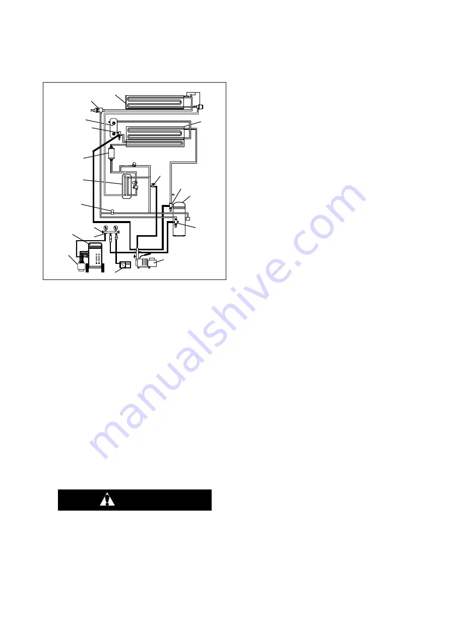
1. Refrigerant Cylinder
2. Refrigerant Recovery
Unit
3. Manifold Gage Set
4. Valve
5. Vacuum Gauge
6. Vacuum Pump
7. Suction Service Valve
8. Compressor
9. Discharge Service
Valve
10. Economizer Service
Line Valve
11. Condenser
12. Evaporator
13. Compressor Suction
Modulation Valve
(CSMV)
14. Receiver
15. Liquid Line Service
Valve
16. Filter Drier
17. Economizer Heat
Exchanger
18. Unloader Solenoid
Valve (USV)
Figure 8-10. Refrigerant System
Service Connections
b. The recommended procedure for finding leaks in a
system is with an electronic leak detector. Testing
joints with soapsuds is satisfactory only for locating
large leaks, or pinpointing small leaks once a gen-
eral area has been located.
CAUTION
Only a refrigerant drum containing R-404A
or R-452A should be connected to this re-
frigeration unit in order to pressurize the
system. However, dry nitrogen may be
used to increase pressure. Any other gas
or vapor will contaminate the system and
require additional purging and evacuation.
c. Ensure the microprocessor message center reads
"RECOVER/LEAK CHK/EVAC MODE" when actual-
ly leak checking.
If system is without refrigerant, pressure, or pres-
sure is below 2.0 bar (30 psig), charge refrigerant
to bring pressure between 2.0 to 3.4 bar (30 to
50 PSIG).
During the charging process, the microprocessor
may switch to the charge mode. If this occurs,
switch it back to the "RECOVER/LEAK CHK/EVAC
MODE" (refer to section 5.1.3). Leak check all con-
nections.
d. Remove the refrigerant charge using a refrigerant
recovery system. If required, repair any leaks and
repeat the leak check. Evacuate and dehydrate the
unit (refer to Section 8.5.4) and then charge unit
with refrigerant. (Refer to Section 8.5.5).
8.5.4 Evacuation
General
Moisture is the deadly enemy of refrigerant systems.
The presence of moisture in a refrigeration system can
have many undesirable effects. The most common are
copper plating, acid sludge formation, "freeze-up" of
metering devices (EVXV or TXV) by free water, and
formation of acids, resulting in metal corrosion.
Preparation
a. Evacuate and dehydrate only after pressure leak
test. (Refer to Section 8.5.3)
b. Essential tools to properly evacuate and dehydrate
any system include a good vacuum pump (5 cfm /
8m
3
H volume displacement, Carrier Transicold
P/N 990071) and a good vacuum indicator such as
a thermocouple vacuum gauge, (Carrier Transicold
P/N 07-60132-00).
NOTE
The use of a compound gauge is not recom-
mended because of its inherent inaccuracy.
c. Keep the ambient temperature above 15.6°C (60°F)
to speed evaporation of moisture. If ambient tem-
perature is lower than 15.6°C (60°F) ice might form
before moisture removal is complete. Heat lamps or
alternate sources of heat may be used to raise sys-
tem temperature.
Procedure
a. Remove the refrigerant charge using a refrigerant
recovery system. Refer to paragraph 8.5.1.
b. The recommended method to evacuate and dehy-
drate the system is to connect four evacuation hos-
es (Do not use standard service hoses, as they are
not suited for evacuation purposes.) as shown in
Figure 8-9.
c. With the economizer service line valve and unit
service valves closed (back seated) and the vacuum
pump and electronic vacuum gauge valves open,
start the pump and draw a deep vacuum. Shut off
the pump and check to see if the vacuum holds.
Summary of Contents for NDK33BN0KB
Page 2: ......
Page 3: ...OPERATION SERVICE MANUAL for VECTOR 1550 1550 CITY Trailer Refrigeration Units...
Page 4: ......
Page 14: ......
Page 22: ...62 61753 21 1 8 1 5 SAFETY DECALS 62 61343 00 Rev or 62 02139 01 Rev C 62 02143 00 Rev...
Page 24: ...62 61753 21 1 10 62 60192 00 Rev D...
Page 30: ...62 61753 21 2 6...
Page 48: ......
Page 212: ......
Page 226: ......
Page 248: ......
Page 252: ......
Page 262: ......
Page 270: ......


