Specifications are subject to change without notice.
22
441 01 3400 02
A190085
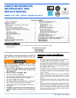
Fig. 26 -- Thermostat Wiring Diagrams
NOTES FOR THERMOSTAT WIRING DIAGRAMS
1. Refer to outdoor equipment Installation Instructions for additional information and setup procedure.
2. Outdoor Air Temperature Sensor must be attached in all dual fuel application.
3. Refer to ICP thermostat Installation Instructions for additional information and setup procedure.
4. HUM 24VAC terminal is 24 VAC and is energized when the low pressure switch closes during a call for heat.
5. When connecting 115 VAC to humidifier use a separate 115 VAC supply.
6. When using a humidifier on a HP installation, connect humidifier to hot water.