background image

10

SYSTEM EVACUATION AND
CHARGING

UNIT DAMAGE HAZARD

Failure to follow this caution may result in equipment
damage or improper operation.

Never use the system compressor as a vacuum pump.

CAUTION

!

Refrigerant tubes and indoor coil should be evacuated using the
recommended deep vacuum method of 500 microns. The alternate
triple evacuation method may be used if the following procedure is
followed. Always break a vacuum with dry nitrogen.

NOTE:  All units (except the 18,000 BTU model) have a Master
Suction and Liquid Line Service Valve.

System Vacuum and Charge

Using Vacuum Pump

1 Completely tighten the flare nuts (A, B, C, D, E). Fully

open all circuits service valves. Connect the manifold gage
charge hose to the charge port of the low side Master service
valve to evacuate all circuits at the same time (see Fig. 8).

2 Connect the charge hose to the vacuum pump.

3 Fully open the low side of manifold gage (see Fig. 9).

4 Start the vacuum pump

5 Evacuate using the triple evacuation method.

6 After evacuation is complete, fully close the low side of

manifold gage and stop the vacuum pump operation.

7 The factory charge contained in the outdoor unit is good for

up to 25ft. (8 m) of line length.

8 Disconnect the charge hose from the charge connection of

the low side service valve.

9 Securely tighten the service valves caps.

Outdoor Unit

Indoor Unit

Refrigerant

Service Valve

Low Side

High Side

A

B

C

D

Fig. 8 – Service Valve

Manifold Gage

500 microns

Low side valve

High side valve

Charge hose

Charge hose

Vacuum pump

Low side valve

Fig. 9 – Manifold

Deep Vacuum Method

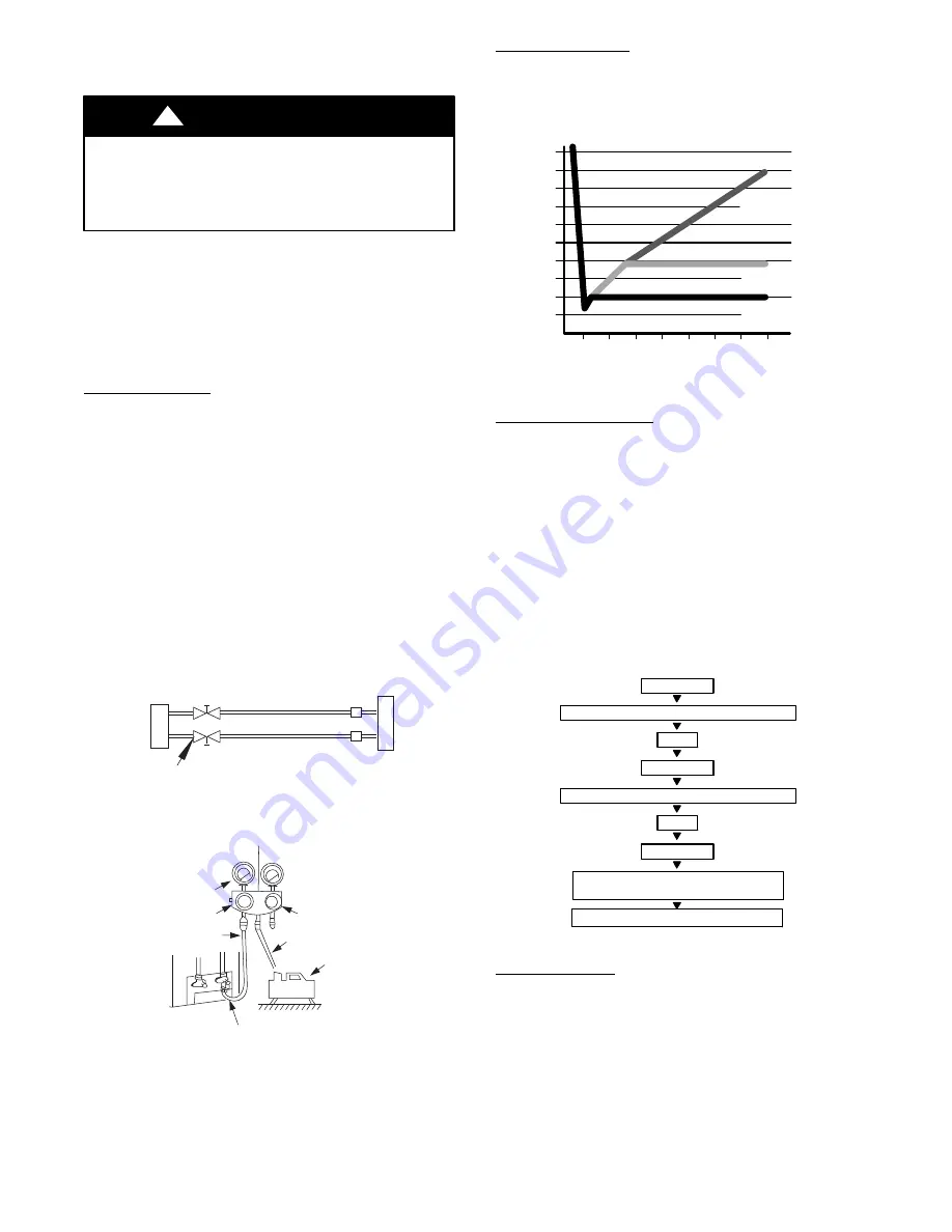
The deep vacuum method requires a vacuum pump capable of
pulling a vacuum of 500 microns and a vacuum gage capable of
accurately measuring this vacuum depth. The deep vacuum method
is the most positive way of assuring a system is free of air and
liquid water (see Fig. 10).

500

MINUTES

0

1

2

3

4

5

6

7

1000

1500

LEAK IN

SYSTEM

VACUUM TIGHT

TOO WET

TIGHT

DRY SYSTEM

2000

MICRONS

2500

3000

3500

4000

4500

5000

Fig. 10 – Deep Vacuum Graph

Triple Evacuation Method

The triple evacuation method should be used. Refer to Fig. 11 and
proceed as follows:

1 Pump system down to 500 MICRONS of mercury and

allow the pump to continue operating for an additional 15
minutes. Unit must maintain 500 microns or less for 30
minutes or more to ensure a dry system.

2 Close the service valves and shut off the vacuum pump.

3 Connect a nitrogen cylinder and regulator to the system and

open until the system pressure is 2 psig.

4 Close the service valve and allow the system to stand for 10

minutes. During this time, dry nitrogen will be able to
diffuse throughout the system absorbing moisture.

5 Repeat this procedure as indicated in Fig. 11. The system

will then be free of any contaminants and water vapor.

CHECK FOR TIGHT, DRY SYSTEM

(IF IT HOLDS DEEP VACUUM)

EVACUATE

BREAK VACUUM WITH DRY NITROGEN

WAIT

EVACUATE

RELEASE CHARGE INTO SYSTEM

BREAK VACUUM WITH DRY NITROGEN

EVACUATE

WAIT

Fig. 11 – Triple Evacuation Method

Final Tubing Check

IMPORTANT:


Check to be certain factory tubing on both

indoor and outdoor unit has not shifted during shipment.
Ensure tubes are not rubbing against each other or any sheet
metal. Pay close attention to feeder tubes, making sure wire ties
on feeder tubes are secure and tight.

Summary of Contents for DHMSHAQ09XA1

Page 1: ...ER WARNING and CAUTION These words are used with the safety alert symbol DANGER identifies the most serious hazards which will result in severe personal injury or death WARNING signifies hazards which...

Page 2: ...L NOT USED INDOOR UNIT DH MS 3 Q DH FAN COIL UNIT MS MODEL VOLTAGE 1 115 1 60 3 208 230 1 60 SYSTEM TYPE Q HEAT PUMP NOMINAL CAPACITY 09 3 4 TON 12 1 TON 18 1 1 2 TONS 24 2 TONS 30 2 1 2 TONS 36 3 TON...

Page 3: ...2 2 3 3 3 Fins per inch 20 20 20 20 20 18 18 18 Circuits 3 3 3 3 4 7 7 7 Indoor Unit Width in mm 32 87 835 32 87 835 32 87 835 32 87 835 38 98 990 46 69 1186 46 69 1186 46 69 1186 Unit Height in mm 11...

Page 4: ...343 13 39 343 13 39 343 Width In mm 32 87 835 32 87 835 32 87 835 32 87 835 38 98 990 46 69 1186 46 69 1186 46 69 1186 Depth In mm 7 80 198 7 80 198 7 80 198 7 80 198 8 58 218 10 16 258 10 16 258 10 1...

Page 5: ...s are line voltage AC power one is communication wiring S and the other is a ground wire Wiring between indoor and outdoor unit is polarity sensitive The use of BX wire is NOT recommended If installed...

Page 6: ...208 230V Notes 1 Do not use thermostat wire for any connection between indoor and outdoor units 2 All connections between indoor and outdoor units must be as shown The connections are sensitive to po...

Page 7: ...09 12 115V Table 6 INDOOR UNIT CONTROL BOARD INPUT or OUTPUT VALUE L_IN Power Voltage AC115V CN11 Power Voltage AC115V CN16 Relative to the N terminal voltage DC 24V CN15 Maximum voltage DC5V CN4 Indo...

Page 8: ...s 09 36 208 230V Table 7 INDOOR UNIT CONTROL BOARD INPUT or OUTPUT VALUE L_IN Power Voltage AC230V CN11 Power Voltage AC230V CN16 Relative to the N terminal voltage DC24V CN15 Maximum voltage DC5V CN4...

Page 9: ...mps REFRIGERANT LINES IMPORTANT Both refrigerant lines must be insulated separately Table 2 lists the pipe sizes for the indoor unit Refer to the outdoor unit installation instructions for other allow...

Page 10: ...Fig 9 Manifold Deep Vacuum Method The deep vacuum method requires a vacuum pump capable of pulling a vacuum of 500 microns and a vacuum gage capable of accuratelymeasuring this vacuum depth The deep...

Page 11: ...hen there is only one malfunctioning temperature sensor the air conditioner keeps working yet displays the error code in case of any emergency use When there is more than one malfunctioning temperatur...

Page 12: ...continues to runs the indoor and outdoor motors stop and the indoor unit defrost lamp illuminates and appears Evaporator Coil Temperature Protection Fig 17 Evaporator Coil Temperature Protection When...

Page 13: ...mpressor delays start up for 1 minute before powering on In other instances the compressor waits three 3 minutes before restarts Refrigerant Leakage Detection With this new technology the display area...

Page 14: ...aying temperature is the actual value 2 The temperature is _C no matter what kind of remote controller is used 3 T1 T2 T3 T4 T2B display range 25 70 TP display range 20 130 4 Frequency display range 0...

Page 15: ...r Electrolytic Capacitors HIGH VOLTAGE CAUTION Fig 19 Electrolytic Capacitors For other models please connect discharge resistance approximately 100 40W or a soldering iron plug between the terminals...

Page 16: ...ge detection H 1 time O F0 Overload current protection H 2 times O F1 Outdoor ambient temperature sensor T4 open circuit or short circuit H 3 times O F2 Condenser coil temperature sensor T3 open circu...

Page 17: ...allation mistake PCB faulty Troubleshooting Yes Replace the indoor outdoor main PCB Power off then restart the unit 2 minutes later EEPROM A read only memory whose contents can be erased and reprogram...

Page 18: ...ulty Troubleshooting Measure Vs is it a positive fluctuation Vs represents the voltage S and N of the outdoor unit Red pan S Black pan N Power off then restart the unit 2 minutes later Replace the ind...

Page 19: ...ing normal the voltage moves alternately between 50V to 50V If the outdoor unit has a malfunction the voltage will move alternately with positive value If the indoor unit has malfunction the voltage w...

Page 20: ...receive a zero crossing signal feedback for 4 minutes or the zero crossing signal time interval is abnormal Supposed causes Connection mistake PCB faulty Troubleshooting Check if the connections and...

Page 21: ...the failure Supposed causes Wiring mistake Fan assembly faulty Fan motor faulty PCB faulty Troubleshooting Power off then restart the unit 2 minutes later Shut off the power supply Rotate the fan by h...

Page 22: ...VOLTAGE 1 Red Vs Vm 140V 190V 2 3 Black GND 0V 4 White Vcc 14 17 5V 5 Yellow Vsp 0 5 6V 6 Blue FG 14 17 5V 2 Outdoor DC Fan Motor control chip is in the outdoor PCB S Power on the unit and check if t...

Page 23: ...he sampling voltage is lower than 0 06V or higher than 4 94V the LED displays the failure Supposed causes Wiring mistake Sensor faulty PCB faulty Troubleshooting Check the connection between the tempe...

Page 24: ...n for 4 seconds and this situation occurs 3 times the display area displays EC and the air conditioner will turn off Supposed causes T2 sensor faulty Indoor PCB faulty System problems such as leakage...

Page 25: ...uses Power supply problems System blockage PCB faulty Wiring mistake Compressor malfunction Troubleshooting Check the power supply Check the connections and wires Stop the unit No Yes No Correct the c...

Page 26: ...ke IPM malfunction Outdoor fan assembly faulty Compressor malfunction Outdoor PCB faulty Troubleshooting Check the wiring between main the PCB and the compressor Correct the connection or replace the...

Page 27: ...27 DIAGNOSIS AND SOLUTION CONT Fig 27 P U Fig 28 P V...

Page 28: ...28 DIAGNOSIS AND SOLUTION CONT Fig 29 P W Fig 30 N U...

Page 29: ...29 DIAGNOSIS AND SOLUTION CONT Fig 31 N V Fig 32 N W...

Page 30: ...sed causes Power supply problems System leakage or block PCB faulty Troubleshooting Check the power supply Check the connections and wires Stop the unit No Yes No Correct the connections or replace th...

Page 31: ...faulty Troubleshooting Check the air flow system of indoor and outdoor units Clear up the air inlet and outlet or the heat exchanger of indoor and outdoor units Yes No Yes Yes Power off then restart t...

Page 32: ...Wiring mistake IPM malfunction Outdoor fan assembly faulty Compressor malfunction Outdoor PCB faulty Troubleshooting Check the wiring between main PCB and compressor Correct the connection or replace...

Page 33: ...CB measure the resistance value with a tester Fig 34 Tester Temperature sensors Room temp T1 sensor Indoor coil temp T2 sensor Outdoor coil temp T3 sensor Outdoor ambient temp T4 sensor Compressor dis...

Page 34: ...71 1 29078 117 243 0 38991 2 28 39 8239 38 100 5 62961 78 172 1 25423 118 244 0 37956 1 30 37 1988 39 102 5 39689 79 174 1 2133 119 246 0 36954 0 32 35 2024 40 104 5 17519 80 176 1 17393 120 248 0 359...

Page 35: ...84 115 239 2 422 4 25 222 8 36 97 34 32 76 169 7 82 116 241 2 357 3 27 211 4 37 99 32 94 77 171 7 566 117 243 2 294 2 28 200 7 38 100 31 62 78 172 7 321 118 244 2 233 1 30 190 5 39 102 30 36 79 174 7...

Page 36: ...201 2 125 257 4 39 2 33 91 4 64 147 2 95 203 126 258 8 4 5 40 1 34 93 2 65 149 96 204 8 127 260 6 5 41 35 95 66 150 8 97 206 6 128 262 4 6 42 8 36 96 8 67 152 6 98 208 4 129 264 2 7 44 6 37 98 6 68 1...

Page 37: ...ANCE VALUE Red Black Several M Red Black Several M P N U N U V V W W Red Indoor AC Fan Motor Measure the resistance value of each winding by using the tester Table 17 Resistance Value POSITION RESISTA...

Page 38: ...l 1 Pull the bottom side of the panel and release the clips Then remove the front panel 2 Remove the filter and horizontal louver 3 Remove the four screws 4 Remove the cover one screw 5 Lift the panel...

Page 39: ...2 Pull out the clip toward the left side and open the cover 3 Remove the securing screw and open the box cover 4 Pull out the connectors of the swing motor and the fan motor 5 Remove the securing scr...

Page 40: ...electrical parts sections 1 and 2 remove the pipe holder at the rear side of the unit 2 Remove the two screws on the evaporator at the base bearing side 3 Remove the two screws on the evaporator at t...

Page 41: ...an and motor How to remove the fan and motor 1 After removing the evaporator assembly see sections 1 3 remove the three 3 screws securing the cover 2 Remove the screw securing the motor and then pull...

Page 42: ...BDP D 7310 W Morris St D Indianapolis IN 46231 Edition Date 11 17 Manufacturer reserves the right to change at any time specifications and designs without notice and without obligations Catalog No SG...

Reviews: