background image

6

6" (0.15m) min.

8"

(0.2m)

min.

6'-8'3"

8"

(0.2m)

min.

(1.8-2.5m)

1

3

2

4

G-2

270

125

260

45

9

45

90

80

635
450
250

66

54

A

09, 12

ALL DIMENSIONS ARE IN mm

G-2

10.63

4.92

10.24

1.77

0.35

1.77

3.5

3.15

25

17.72

9.84

2.6

2.1

A

09, 12

ALL DIMENSIONS ARE IN inches

2.5

64

2.5-IN.

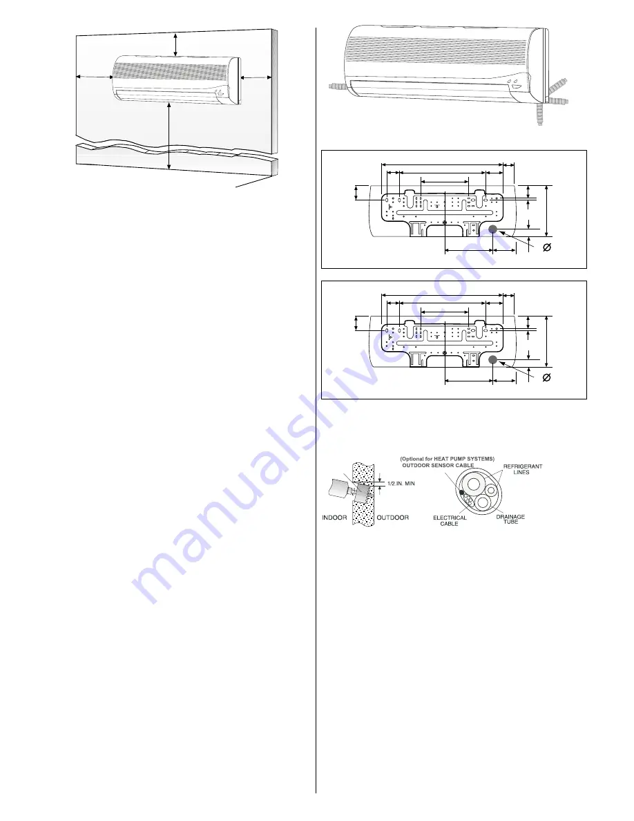
Fig. 2 — Indoor Unit Clearances

INSTALLATION

Plan the installation carefully to avoid component failures

and make installation easier.

Indoor Unit Installation

REFRIGERANT LINE ROUTING — The refrigerant lines may
be routed in any of the four directions shown in Fig. 3.

INSTALL THE MOUNTING BRACKET

1. Carefully  remove   the   mounting  bracket,  which  is

connected to the back of the indoor unit's base with screws.

2. Position the mounting bracket on the wall and level it

using a spirit level (see Fig. 2 for minimum required
clearance distances).

3. Mark the four drilling holes on the wall, as they appear in

Fig. 4.

4. Drill the holes, insert the wall plugs and use four long

screws to attach the mounting bracket to the wall.

5. Check that the bracket is leveled and securely fastened to

the wall.

DRILL A HOLE IN THE WALL FOR DRAINAGE
AND INTER-UNIT CONNECTIONS-

To make the connections between the indoor and outdoor units,
drill a 2.5-in. hole through the wall for the refrigerant lines, drain-
age hose and control cable passage as shown in Fig. 5.

1. Mark the center of the hole to be drilled according to the

refrigerant line routing used and dimensions shown in Fig.
4.

2. Make sure to drill outwards and downwards, so that the

opening in the outside wall is at least 1/2" lower than the
opening on the inside.

3. Make sure the drainage hose is at the bottom side of the

hole.

4 . If refrigerant line route no. 1,2 or 4 are used, use a small

saw blade to carefully remove the corresponding plastic
covering on the side panel.

5. Run the outdoor sensor cable, electrical cable, refrigerant

lines, and drainage tube through the hole.

6. Fill the remaining wall hole gap with an appropriate

sealant material.

 Fig. 3 — Refrigerant Lines

Fig. 4 — Mounting Bracket 38BNC/BNQ 009, 012

Fig. 5 — Drill Holes

Summary of Contents for BCC018

Page 1: ...al Data System Requirements IMPORTANT The Indoor units the inter units cable voltage is 30 VDC IMPORTANT Each refrigerant line must be insulated Separately See line sizing requirements in tabel 2 Cons...

Page 2: ...IAGRAM Mounting Bracket 2 X 1 Long Screws 2 X 8 Outdoor Sensor Connecting Cable 2 X 1 Available for HEAT PUMP ONLY Absorption Cushions 4 Electric Terminals 2 X 8 2 X Remote Controller 1 Mounting Mount...

Page 3: ...NQ012 COOLING CAPACITY Btuh 2 X 9 000 2 X 11 400 SEER 13 0 13 0 HEATING CAPACITY Btuh 17 200 23 600 HSPF 7 7 7 7 SYSTEM CHARGE Ib 2 X 2 4 2 X 3 1 MOISTURE REMOVAL pt hr 2 X 2 6 2 X 4 5 AIRFLOW 3 Speed...

Page 4: ...nch mm FRONT VIEW RIGHT SIDE VIEW BOTTOM VIEW LEFT SIDE VIEW TOP VIEW A C B 20 06 2006 GAD L EITANC NEW 815 260 185 635 230 40 12 7 6 35 27 50 32 08 10 23 7 28 25 9 06 1 57 1 2 1 4 1 06 1 96 815 260 1...

Page 5: ...R EITANC SUPERSEDES NEW 38BCC BCQ 018 024 101 CONDENSING UNITS REV TOP VIEW AIR DISCHARGE AIR IN VIEW MINIMUM CLEARANCES SEE NOTE 1 MOUTING SLOT FIELD POWER CONNECTION CONTROL CONNECTION UNDER THIS CO...

Page 6: ...four long screws to attach the mounting bracket to the wall 5 Check that the bracket is leveled and securely fastened to the wall DRILL A HOLE IN THE WALL FOR DRAINAGE AND INTER UNIT CONNECTIONS To m...

Page 7: ...p the cables back 1 4 inch 2 Remove the unit s front panel by lifting the lower part and pulling it gently outward and upward See Fig 6 3 Remove the two screws from the control box cover and take off...

Page 8: ...all the connections are made Bend tubing with special bending tools to avoid the forma tion of sharp bends Take care to avoid kinks or flattening of the tubing Keep the tubing free of dirt sand moist...

Page 9: ...ns to eliminate contamination and moisture 3 Disconnect the vacuum pump Unit should maintain 500 microns for 5 minutes 4 Remove the service port caps from the mixed phase valve and suction line valve...

Page 10: ...both sections NOTE Specifications and performance data are subject to change without notice Table 5 Electrical Data Outdoor Units 115 1 60 UNIT VOLTAGE MCA MOCP FULL LOAD FAN MOTOR COMPRESSOR COMPRES...

Page 11: ...D O O R U N I T TH2 WH YEL GREEN RED J12 J6 J7 J8 FAN RVS COMP J18 K6 K5 K1 K2 STEPPER MOTOR K8 K9 K7 J11 J14 BLK RED 1 3 12V 12V BLK WH RED GREEN BLDC MOTOR J1 J5 1 3 J3 J4 TH1 TAC 670 control TAC 6...

Page 12: ...YEL 2 3 4 6 5 TB H L T V 1 OR GND BLK I N D O O R U N I T TH2 WH GREEN RED J12 J6 J7 J8 FAN RVS COMP J18 K6 K5 K1 K2 STEPPER MOTOR K8 K9 K7 J11 J14 BLK RED 1 3 12V 12V BLK WH RED GREEN BLDC MOTOR J1 J...

Page 13: ...rt and debris from drain holes in base of unit Fan motors are waterproof WARNING Indoor Units To avoid the possibility of electric shock before performing any cleaning and maintenance operations alway...

Page 14: ...harge Check thermistors TH1 and TH2 for correct resistance Check system pressures 4 Flashes High Pressure Check refrigerant charge Check thermistors TH1 and TH2 for correct resistance Check operating...

Page 15: ...41 0 5 1 8 1 0 10 40 10 80 11 21 42 8 6 1 8 1 0 9 986 10 370 10 76 44 6 7 1 8 1 0 9 595 9 960 10 33 46 4 8 1 8 1 0 9 222 9 569 9 921 48 2 9 1 8 1 0 8 866 9 196 9 530 50 0 10 1 8 1 0 8 526 8 840 9 157...

Page 16: ...2 055 2 137 2 220 123 8 51 2 3 1 3 1 990 2 070 2 151 125 6 52 2 3 1 3 1 928 2 006 2 085 127 4 53 2 3 1 3 1 867 1 943 2 021 129 2 54 2 3 1 3 1 809 1 883 1 959 131 0 55 2 5 1 4 1 753 1 826 1 900 132 8...

Page 17: ...oor fan motor In Heat mode Delayed start for indoor fan motor Normal software delay maximum of 20 sec Clogged air filters Clean filters Lack of refrigerant Ice formation on the evaporator coil Unit mu...

Reviews: