background image

27

9.4 - Refrigerant system

Verify air and water flow rates are at proper levels before
servicing. To maintain sealed circuitry integrity, do not install
service gauges unless unit operation appears abnormal.

Check to see that unit is within the superheat and subcooling
temperature ranges shown in Table 16. If the unit is not within
these ranges, recover and reweigh in refrigerant charge.

9.5 - Condensate drain cleaning

Clean the drain line and unit drain pan at the start of each cooling
season. Check flow by pouring water into drain. Be sure trap is
filled to maintain an air seal.

9.6 - Air coil cleaning

Remove dirt and debris from evaporator coil as required by
condition of the coil. Clean coil with a stiff brush, vacuum
cleaner, or compressed air. Use a fin comb of the correct tooth
spacing when straightening mashed or bent coil fins.

9.7 - Condenser cleaning

Water-cooled condensers may require cleaning of scale (water
deposits) due to improperly maintained closed-loop water
systems. Sludge build-up may need to be cleaned in an open
water tower system due to induced contaminants.

Local water conditions may cause excessive fouling or pitting
of tubes. Condenser tubes should therefore be cleaned at least
once a year, or more often if the water is contaminated.

Proper water treatment can minimise tube fouling and pitting. If
such conditions are anticipated, water treatment analysis is
recommended. Refer to the Carrier System Design Manual,
Part 5, for general water conditioning information.

CAUTION: Follow all safety codes. Wear safety glasses and
rubber gloves when using inhibited hydrochloric acid solution.
Observe and follow acid manufacturer’s instructions.

Clean condensers with an inhibited hydrochloric acid solution.
The acid can stain hands and clothing, damage concrete, and,
without inhibitor, damage steel. Cover surroundings to guard
against splashing. Vapours from vent pipe are not harmful, but
take care to prevent liquid from being carried over by the gases.

Warm solution acts faster, but cold solution is just as effective if
applied for a longer period.

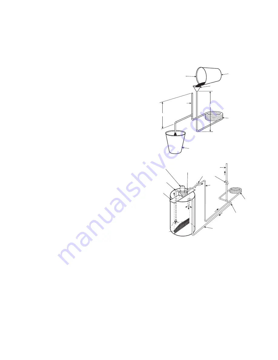
9.7.1 - Gravity flow method
Do not add solution faster than vent can exhaust the generated
gases.

When condenser is full, allow solution to remain overnight,
then drain condenser and flush with clean water. Follow acid
manufacturer’s instructions (see Fig. 18).

9.7.2 - Forced circulation method
Fully open vent pipe when filling condenser. The vent may be
closed when condenser is full and pump is operating (see Fig. 19).

Regulate flow to condenser with a supply line valve. If pump is
a non-overloading type, the valve may be fully-closed while
pump is running.

For average scale deposit, allow solution to remain in condenser
overnight. For heavy scale deposit, allow 24 hours. Drain con-
denser and flush with clean water. Follow acid manufacturer’s
instructions.

Fig. 18 - Gravity flow method

Fig. 19 - Forced circulation method

9.8 - Checking system charge

Units are shipped with full operating charge. If recharging is
necessary:
1.

Insert thermometer bulb in insulating rubber sleeve on
liquid line near filter drier. Use a digital thermometer for
all temperature measurements. DO NOT use a mercury or
dial-type thermometer.

2.

Connect pressure gauge to discharge line near compressor.

3.

After unit conditions have stabilised, read head pressure
on discharge line gauge.

NOTE: Operate unit a minimum of 15 minutes before checking
charge.

4.

From standard field-supplied pressure-temperature chart
for R-407C, find equivalent bubble point temperature.

5.

Read liquid line temperature on thermometer; then
subtract from bubble point temperature. The difference
equals subcooling temperature.

FILL CONDENSER WITH
CLEANING SOLUTION. DO
NOT ADD SOLUTION
MORE RAPIDLY THAN
VENT CAN EXHAUST
GASES CAUSED BY
CHEMICAL ACTION.

PAIL

FUNNEL

CONDENSER

PAIL

3’ TO 4’

VENT
PIPE

5’ APPROX

1”
PIPE

Fill condenser with cleaning
solution. Do not add solution
more rapidly than vent can
exhaust gases caused by
chemical action.

Pail

Funnel

25 mm
pipe

1.5 m approx.

Condenser

Pail

Vent pipe

0.9 to 1.2 m

Pump

Suction

Pump
support

Tank

Fine mesh
screen

Return

Remove water
regulating valve

Condenser

25 mm
pipe

Supply

Globe
valves

Gas vent

Priming
connection

Summary of Contents for Aquazone 50RHE 006

Page 1: ...ting in the Eurovent Certification Programme Products are as listed in the Eurovent Directory of Certified Products 50RHE 006 060 Water Source Heat Pumps Horizontal Units Installation OperationandMaintenanceInstructions TM ...

Page 2: ...or rotation 21 6 3 Unit start up cooling mode 21 6 4 Unit start up heating mode 21 6 5 Flow regulation 21 6 6 Flushing 22 6 7 Anti freeze 23 6 8 Cooling tower boiler systems 23 6 9 Ground coupled closed loop and plateframe heat exchanger well systems 23 7 OPERATION 24 7 1 Power up mode 24 7 2 Units with Aquazone Complete C control 24 7 3 Units with Aquazone Deluxe D control 24 8 SYSTEM TEST 25 8 1...

Page 3: ...ith each unit Before unit start up read all manuals and become familiar with the unit and its operation Thoroughly check out the system before operation Complete the inspections and instructions listed below to prepare a unit for installation See Table 1 for unit physical data Horizontal units are designed for indoor installation only Be sure to allow adequate space around the unit for servicing S...

Page 4: ...tion isolators must have bolts loosened and shipping clamps removed 7 Remove any blower support cardboard from inlet of the blower 8 Locate and verify any accessory kit located in compressor section 9 Remove any access panel screws that may be difficult to remove once unit is installed Table 1 Physical data 50RHE 006 009 012 015 019 024 030 036 042 048 060 Cooling capacity kW 1 5 2 1 2 5 3 9 4 9 5...

Page 5: ...t orientation is determined by looking at water connection side front N P M O 3 F K L 2 1 E A C V U B T S F N P M O 27 9 C V T S U B X Y Z A C R P Q O 82 6 O A C P Q R D 82 6 J 5 Left return 610 mm service access Front CSP Optional 610 mm service access Left return ASP Right discharge Back discharge Condensate 3 4 FPT Power supply 3 4 knockout 1 2 knockout Low voltage 1 2 knockout CAP Front view 8...

Page 6: ...al for supply and return piping Water out Water in Low pressure drop water control valve optional field installedaccessory Balancing valve field installedand calibratedaccessory Water in Water out Supply loop Return loop Return air ductwork not shown 3 8 threaded rods by others Filter access Unit hanger isolation detail 3 8 threaded rod by others Vibration isolator white compressor end and red blo...

Page 7: ...turn models in the field due to refrigerant piping changes Preparation The unit should be on the ground in a well lit area for conversion Hung units should be taken down to ground level before con verting Side to back discharge conversion 1 Remove screws to free the top and discharge panels see Fig 3 2 Remove the access panel and set aside 3 Lift the discharge panel from side of unit and rotate it...

Page 8: ...y be required for the ventilating air supply If hard ducted ven tilation is not required be sure that a proper air path is provi ded for ventilation air to unit to meet ventilation requirement of the space Fig 5 Horizontal hanger bracket factory installed 50RHE Dimensions mm A B C D E 006 024 568 1095 619 1095 516 030 036 568 1349 619 1349 518 042 048 568 1577 619 1577 518 060 645 1806 695 1806 59...

Page 9: ...flow verification In addition to complying with any applicable codes consider the following for system piping Piping systems using water temperatures below 10 C require 13 mm closed cell insulation on all piping surfaces to eliminate condensation Avoid all plastic to metal threaded fittings due to the potential to leak Use a flange fitted substitute Teflon tape thread sealant is recommended to min...

Page 10: ... 12 for a schematic of the field connections which must be made by the installing or electrical contractor Refer to electrical data for fuse sizes Consult the unit wiring diagram located on the inside of the compressor access panel to ensure proper electrical hookup The installing or electrical contractor must make the field connections when using field supplied disconnect Operating voltage must b...

Page 11: ...4 V alarm signal shown For dry alarm contact cut JW1 jumper and dry contact will be available between AL1 and AL2 7 Transformer secondary ground via microprocessor board stand offs and screws to control box Ground available from top two stand offs as shown 8 Fan motors factory wired for medium speed For high or low speed remove BLU wire from fan motor speed tap M and connect to H for high or L for...

Page 12: ...to thermostat installation instructions for wiring to the unit 6 24 V alarm signal shown For dry alarm contact cut JW1 jumper and dry contact will be available between AL1 and AL2 7 Transformer secondary ground via microprocessor board stand offs and screws to control box Ground available from top two stand offs as shown 8 Fan motors factory wired for medium speed For high or low speed remove BLU ...

Page 13: ...unit must comply with local codes 3 Transformer is wired to 240 V ORG lead for 240 1 50 units switch RED and ORG leads to PB 1 and insulate ORG lead for 220 1 50 4 FP1 thermistor provides freeze protection for water When using anti freeze solutions cut JW3 jumper 5 Check installation wiring information for specific thermostat hook up Refer to thermostat installation instructions for wiring to the ...

Page 14: ...ia microprocessor board stand offs and screws to control box Ground available from top two stand offs as shown 8 Blower motor is factory wired for medium and high speeds For any other combination of speeds at the motor attach black wire to the higher of the two desired speed taps and the blue wire to the lower of the two desired speed taps 9 Blower motor is factory wired for high and low speeds No...

Page 15: ...nit must be within voltage range indicated on unit nameplate On 3 phase units voltages under load between phases must be balanced within 2 Use the following formula to determine the percentage voltage imbalance voltage imbalance 100 x Example Supply voltage is 460 3 60 AB 452 Volts BC 464 Volts AC 455 Volts Average voltage 457 Determine maximum deviation from average voltage AB 457 452 5 V BC 464 ...

Page 16: ... 118 104 015 212 160 High 345 316 288 250 198 Medium 321 302 274 241 189 Low 293 278 255 222 179 019 264 198 High 326 311 283 250 203 Medium 302 288 260 227 189 Low 293 269 245 217 179 024 307 231 High 396 368 335 302 260 Medium 387 359 326 297 255 Low 368 340 311 278 231 030 349 264 High 529 496 463 425 378 330 Medium 510 477 448 415 368 326 Low 458 439 406 378 340 297 036 437 326 High 614 576 57...

Page 17: ...n Fig 17 Aslow closing valve may be required to prevent water hammer When using a slow closing valve consider special wiring conditions The valve takes approximately 60 seconds to open very little water will flow before 45 seconds and it activates the compressor only after the valve is completely opened by closing its end switch When wired as shown the valve will have the following operating chara...

Page 18: ...emp to choose FP1 limit of 12 2 C or 1 1 C To select 1 1 C as the limit DO NOT clip the jumper To select 12 2 C as the limit clip the jumper Air coil freeze protection FP2 limit setting Select jumper 2 JW2 FP2 low temp to choose FP2 limit of 12 2 C or 1 1 C To select 1 1 C as the limit DO NOT clip the jumper To select 12 2 C as the limit clip the jumper Alarm relay setting Select jumper 1 JW1 AL2 ...

Page 19: ...cooling stage 2 Select ON for normal mode The fan speed relay will turn on during cooling stage 2 in normal mode Switch 6 Not used Boilerless operation Switch 7 provides selection of boilerless operation and works in conjunction with switch 8 In boilerless operation mode only the compressor is used for heating when FP1 is above the boilerless changeover temperature set by switch 8 below Select ON ...

Page 20: ...ir will adversely affect the unit performance reliability and service life Power supply A voltage variation of 10 of nameplate utilisation voltage is acceptable Unit starting conditions Depending on the model units start and operate in an ambient temperature of 7 2 C with entering air temperature at 4 4 C or 10 C entering water temperature at 6 7 C or 10 C and with both air and water at the flow r...

Page 21: ... 8 Water temperature change through heat exchanger Water flow rate l s Cooling rise K Heating drop K Min Max Min Max For closed loop ground source or cooling boiler systems at 0 054 l s per kW 5 6 7 2 2 4 4 For open loop ground water systems 0 027 l s per kW 11 1 14 4 5 6 9 4 6 4 Unit start up heating mode NOTE Operate the unit in heating cycle after checking the cooling cycle Allow five minutes b...

Page 22: ...12 3 11 7 0 568 26 9 25 4 23 6 22 4 0 757 44 0 41 0 38 3 36 5 060 0 473 33 5 31 4 29 3 27 8 0 713 58 3 54 4 50 8 48 4 0 947 88 5 82 8 77 1 73 3 6 6 Flushing Once the piping is complete units require final purging and loop charging A flush cart pump of at least 1 12 kW is needed to achieve adequate flow velocity in the loop to purge air and dirt particles from the loop Flush the loop in both direct...

Page 23: ...lume l per 30 m of pipe Pipe Diameter in Volume l Copper 1 15 5 1 25 24 2 1 5 34 8 Rubber hose 1 14 7 Polyethylene 3 4 IPS SDR11 10 6 1 IPS SDR11 17 0 1 1 4 IPS SDR11 30 0 1 2 IPS SDR11 41 2 2 IPS SDR11 68 1 1 1 4 IPS SCH40 31 4 1 1 2 IPS SCH40 41 2 2 IPS SCH40 64 3 Legend IPS Internal pipe size SCH Schedule SDR Standard dimensional ratio Note Volume of heat exchanger is approximately 3 78 litres ...

Page 24: ... fan enable and compressor relays are remain on The fan speed relay is turned on immediately and turned off immediately once the demand is removed The control reverts to heating stage 1 mode If there is a master slave or dual compressor application all compressor relays and related func tions will operate per their associated DIP switch 2 setting on S1 7 3 4 Heating stage 3 In heating stage 3 mode...

Page 25: ...fast flashes followed by a 10 second pause This sequence will repeat continually until the fault is cleared Table 14 C control LED code and fault descriptions LED code Fault Description 1 No fault in memory There has been no fault since the last power down to power up sequence 2 High pressure switch HP open instantly 3 Low pressure switch LP open for 30 continuous seconds before or during a call b...

Page 26: ...t system refrigerant circuit oil will remain in the compressor To avoid leakage of compressor oil the refrigerant lines of the compressor must be sealed after it is removed IMPORTANT All refrigerant discharged from this unit must be recovered without exception Technicians must follow industry accepted guidelines and all local state and federal statutes for the recovery and disposal of refrigerants...

Page 27: ...ion acts faster but cold solution is just as effective if applied for a longer period 9 7 1 Gravity flow method Do not add solution faster than vent can exhaust the generated gases When condenser is full allow solution to remain overnight then drain condenser and flush with clean water Follow acid manufacturer s instructions see Fig 18 9 7 2 Forced circulation method Fully open vent pipe when fill...

Page 28: ...ide motor bracket assembly to extreme right and lift out through space between fan scroll and side frame Rest motor on a high platform such as a step ladder Do not allow motor to hang by its power wires 10 TROUBLESHOOTING Figs 20 and 21 and Table 16 When troubleshooting problems with a water source heat pump consider the following 10 1 Thermistor A thermistor may be required for single phase units...

Page 29: ...ture out of range Too much cold vent air Bring entering air temperature within design parameters X Improper freeze protect setting Normal airside applications will require 1 1 C only 1 1 C vs 12 2 C X X Bad thermistor Check temperature and impedance correlation Condensate fault code 6 X X Blocked drain Check for blockage and clean drain X X Improper trap Check trap dimensions and location ahead of...

Page 30: ...ersized Recheck loads and sizing check sensible cooling load and heat pump capacity X X Scaling in water heat exchanger Perform scaling check and clean if necessary X X Inlet water too hot or cold Check load loop sizing loop backfill ground moisture High head pressure X Reduced or no airflow in heating Check for dirty air filter and clean or replace Check fan motor operation and airflow restrictio...

Page 31: ...NSION VALVE C C AIR COIL C kPa C kPa LOOK UP PRESSURE DROP IN TABLE 10 TO DETERMINE FLOW RATE C LIQUID LINE kPa C DEW POINT Air coil Expansion valve Heat exchanger Look up pressure drop in Table 10 to determine flow rate Dew point Suction Compressor Discharge SUCTION COMPRESSOR DISCHARGE COAX EXPANSION VALVE C C AIR COIL C kPa C kPa LOOK UP PRESSURE DROP IN TABLE 10 TO DETERMINE FLOW RATE C LIQUID...

Page 32: ... phase scroll compressor is present verify proper rotation per instructions Y N __________ Unit voltage cooling operation Phase AB Volts ________ Phase BC Volts ________ Phase CA Volts ________ if 3 phase if 3 phase Phase AB Amps ________ Phase BC Amps ________ Phase CAAmps ________ if 3 phase if 3 phase Control voltage Is the control voltage above 21 6 Volts Y N __________ If not check for proper...

Reviews: