


72
EVAPORATOR RETUBING
When retubing is required, obtain the service of qualified per-
sonnel experienced in boiler maintenance and repair. Most
standard procedures can be followed when retubing the evapo-
rators. An 8% crush is recommended when rolling replacement
tubes into the tube sheet. Place one drop of Loctite No. 675 or
equivalent on top of tube prior to rolling. This material is in-
tended to “wick” into the area of the tube that is not rolled into
the tube sheet, and prevent fluid from accumulating between
the tube and the tube sheet. New tubes must also be rolled into
the center tube sheet to prevent circuit to circuit leaks.
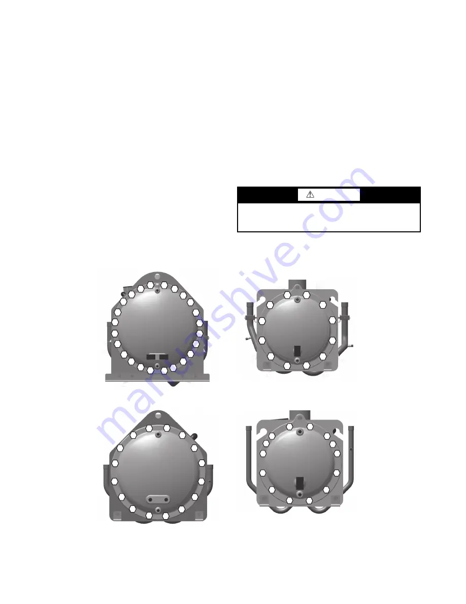
TIGHTENING EVAPORATOR HEAD BOLTS
Preparation
When reassembling evaporator heads, always check the condi-
tion of the O-rings first. The O-ring should be replaced if there
are visible signs of deterioration, cuts or damage. Apply a thin
film of grease to the O-ring before installation. This will aid in
holding the O-ring in the groove while the head is installed.
Torque all bolts to the following specification and in sequence:
5
/
8
-in. Diameter Perimeter Bolts (Grade 5). . . . 150 to 170 ft-lb
(203 to 230 N-m)
3
/
4
-in. Diameter Perimeter Bolts (Grade 5). . . . 200 to 225 ft-lb
(271 to 305 N-m)
1. Install all bolts finger tight.
2. Bolt tightening sequence is outlined in Fig. 69. Follow the
numbering or lettering sequence so that pressure is evenly
applied to O-ring.
3. Apply torque in one-third steps until required torque is
reached. Load
all
bolts to each one-third step before pro-
ceeding to next one-third step.
4. No less than one hour later, retighten all bolts to required
torque values.
5. After refrigerant is restored to system, check for refrigerant
leaks using recommended industry practices.
6. Replace evaporator insulation.
INSPECTING/CLEANING HEAT EXCHANGERS
Inspect and clean evaporator tubes at the end of the first operat-
ing season. Because these tubes have internal ridges, a rotary-
type tube cleaning system is necessary to fully clean the tubes.
Tube condition in the evaporator will determine the scheduled
frequency for cleaning, and will indicate whether water treat-
ment is adequate in the chilled water/brine circuit. Inspect the
entering and leaving water thermistor wells for signs of corro-
sion or scale. Replace the well if corroded or remove any scale
if found.
Fig. 69 — Flooded Evaporator Unit Head Recommended Bolt Torque Sequence
CAUTION
Hard scale may require chemical treatment for its preven-
tion or removal. Consult a water treatment specialist for
proper treatment procedures.
4
2
6
10
14
1
8
2
3
21
17
15
11
7
3
1
5
9
1
3
17
19
24
22
16
12
8
4
2
6
10
14
15
11
7
3
1
5
9
1
3
16
12
8
24" EVAPORATOR – 5/
8
" BOLT
S
(
3
0XA
3
50M THRU
3
0XA500M)
20" & 1
8
" EVAPORATOR –
3
/4" BOLT
S
(
3
0XA200M THRU
3
0XA
3
50
S
)
4
2
6
10
11
7
3
1
5
9
12
8
16" EVAPORATOR –
3
/4" BOLT
S
(
3
0XA160M THRU
3
0XA200
S
)
4
2
6
10
14
11
7
3
1
5
9
1
3
12
8
14" EVAPORATOR –
3
/4" BOLT
S
(
3
0XA140
S
THRU
3
0XA160
S
)
Summary of Contents for AquaForce 30XV140
Page 79: ...79 Fig 76 VFD Communication Wiring Compressor A B Fan VFD A1 A2 B1 B2...
Page 228: ...228 Fig 90 30XV Typical Field Wiring Schematic cont...
Page 229: ...229 Fig 91 30XV Standard Tier 140 275 All Voltages Power Schematic NOTE See Legend on page 226...
Page 230: ...230 Fig 92 30XV Standard Tier 300 325 All Voltages Power Schematic NOTE See Legend on page 226...
Page 240: ...240 Fig 99 30XV Communication Wiring...
Page 241: ...241 Fig 100 30XV 115V Control Wiring All Tonnages All Voltages...
Page 242: ...242 Fig 101 30XV 24V Control Wiring 30XV140 325 All Voltages...
Page 243: ...243 Fig 101 30XV 24V Control Wiring 30XV140 325 All Voltages cont...
Page 244: ...244 Fig 102 30XV 24V Control Wiring 30XV350 500 All Voltages...
Page 245: ...245 Fig 102 30XV 24V Control Wiring 30XV350 500 All Voltages cont...
Page 246: ...246 Fig 103 Component Arrangement Diagram for 30XV140 325...
Page 247: ...247 Fig 103 Component Arrangement Diagram for 30XV140 325 cont...
Page 248: ...248 Fig 104 Component Arrangement Diagram for 30XV350 500...
Page 337: ...337 APPENDIX J FACTORY SUPPLIED PUMPS cont Fig L System Information...
Page 338: ...338 APPENDIX J FACTORY SUPPLIED PUMPS cont Fig M Unit and Language Settings...
Page 341: ...341 APPENDIX J FACTORY SUPPLIED PUMPS cont Fig P Data Input 2...
Page 342: ...342 APPENDIX J FACTORY SUPPLIED PUMPS cont Fig Q Data Input 3...
Page 347: ...347 APPENDIX J FACTORY SUPPLIED PUMPS cont Fig U Pump Wiring Diagram...


