


46
Ice Storage Operation
Chiller operation can be configured to make and store ice. The en-
ergy management module and an Ice Done Switch are required for
operation in the Ice Mode. In this configuration, the machine can
operate with up to three cooling set points: Cooling Setpoint 1 is
used during the Occupied period, Cooling Setpoint 2 is used
during the Unoccupied period when the ice build is complete (Ice
Done Switch is closed), and Cooling Ice Setpoint is used during
the unoccupied period while ice is building (Ice Done Switch is
open). Refer to the 30XV Typical Field Wiring Schematic figure
on page 227 for Ice Done Switch wiring.
To configure this option with the Carrier Controller display:
Broadcast Configuration
The 30XV chiller with Greenspeed
®
Intelligence is capable of
broadcasting OAT, time, date, and holiday status to all elements in
the CCN system. In the stand-alone mode, broadcast must be acti-
vated to utilize holiday schedules and adjust for daylight saving
time. If the chiller is to be connected to a CCN system, determine
which system element is to be the network broadcaster and acti-
vate broadcast in all other system elements. Broadcast is activated
and deactivated in the Carrier Controller Broadcast Menu (
Main
Menu
Configuration Menu
Broadcast Menu
Brocasts
).
Only one element should be configured as a broadcaster. If a
broadcast is activated by a device that has been designated as a
network broadcaster, then broadcast time, date, and holiday status
will be updated over the CCN system. If broadcast is enabled, a
broadcast acknowledger must also be enabled. The acknowledger
cannot be the same machine as the broadcasting machine.
ACTIVATE
The Activate variable enables the broadcast function of the Carrier
Controller controls. If this variable is set to 0, this function is not
used and holiday schedules and daylight savings compensation are
not possible. Setting this variable to 1 allows the machine to
broadcast and receive broadcasts on the network. The following
information is broadcast: the time with compensation for daylight
savings, date, holiday flag, and the Outdoor Air Temperature.
Set this variable to 2 for stand-alone OAT broadcast. With this
configuration, daylight saving time and holiday determination
will be done without broadcasting through the bus.
To configure this option with the Carrier Controller display:
OAT BROADCAST
To enable the OAT broadcast, the unit broadcasting the tempera-
ture must be configured with its own CCN Bus and CCN Address.
Leaving the parameters at the factory default of 0 for the CCN Bus
and CCN Address disables the OAT Broadcast function. Once
configured, the first broadcast of OAT will be within 5 minutes.
To configure this option with the Carrier Controller display:
BROADCAST ACKNOWLEDGER
This configuration defines if the chiller will be used to ac-
knowledge broadcast messages on the CCN bus. One broadcast
acknowledger is required per bus, including secondary buses
created by the use of a bridge. The broadcast acknowledger
must be configured through the Network Service Tool.
Alarm Control
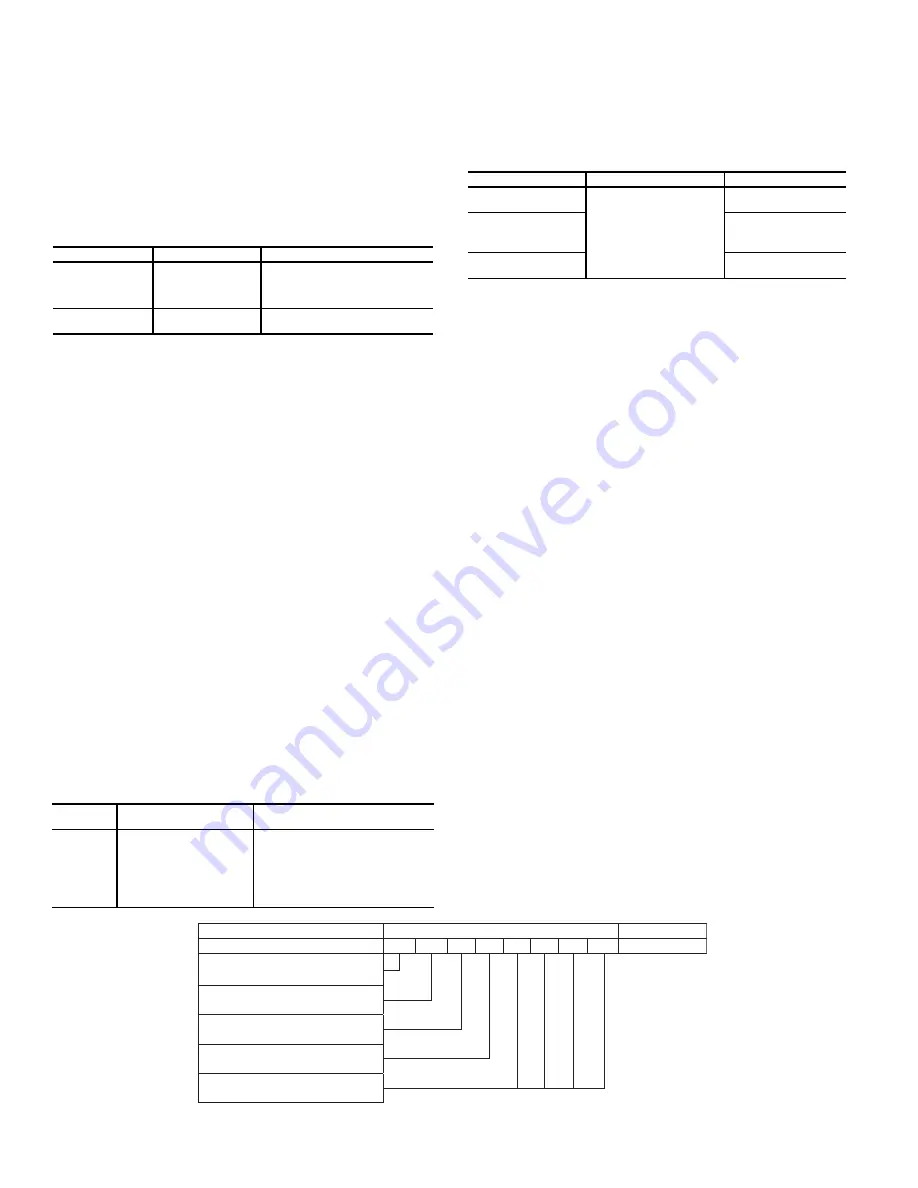
ALARM ROUTING CONTROL
Alarms recorded on the chiller can be routed through the CCN. To
configure this option, the Carrier Controller controls must be con-
figured to determine which CCN elements will receive and pro-
cess alarms. Input for the decision consists of eight digits, each of
which can be set to either 0 or 1. Setting a digit to 1 specifies that
alarms will be sent to the system element that corresponds to that
digit. Setting all digits to 0 disables alarm processing. The factory
default is 00000000. See Fig. 44. The default setting is based on
the assumption that the unit will not be connected to a network. If
the network does not contain a ComfortVIEW™, Comfort-
WORKS
™
, TeLink, DataLINK™, or BACLink module, enabling
this feature will only add unnecessary activity to the CCN com-
munication bus.
Typical configuration of the Alarm Routing variable is
11010000. This Alarm Routing status will transmit alarms to
ComfortVIEW
™
software, TeLink, BACLink, and DataLINK.
This option cannot be configured with the Carrier Controller
display. To change the alarm control routing through the Net-
work Service Tool, navigate to point
ALRM_CNT
in table
ALARMDEF
.
Fig. 44 — Alarm Routing Control
DISPLAY NAME
PATH
VALUE
Ice Mode
Enable
Main Menu
Configuration Menu
General Configura-
tion
Drop Down Selection (YES/NO)
Default = No
Cooling Ice
Setpoint
Main Menu
Setpoint Table
Default = 44°F (6.7°C)
Range = –20 to 78.8°F (–29 to 26°C)
DISPLAY
NAME
PATH
VALUE
Activate
Main Menu
Configuration Menu
Broadcast Menu
Brocasts
0 = Disabled
1 = Broadcast time, date, holiday
flag, and OAT
2 = OAT broadcast only (Daylight
savings time and holiday determina-
tion will be done without broadcast-
ing through the bus)
DISPLAY NAME
PATH
VALUE
Activate
Main Menu
Configuration Menu
Broadcast Menu
Brocasts
Range = 0 to 2
Default = 2
OAT Broadcast
Bus #
Range = 0 to 239
Default = 0
Element #
Range = 0 to 239
Default = 0
DE
S
CRIPTION
S
TATU
S
POINT
Al
a
rm Ro
u
ting
0 0 0 0 0 0 0 0 ALRM_CNT
ComfortVIEW™ or ComfortWORK
S
™
TeLink
Un
us
ed
BACLink or D
a
t
a
LINK™
Un
us
ed
Summary of Contents for AquaForce 30XV140
Page 79: ...79 Fig 76 VFD Communication Wiring Compressor A B Fan VFD A1 A2 B1 B2...
Page 228: ...228 Fig 90 30XV Typical Field Wiring Schematic cont...
Page 229: ...229 Fig 91 30XV Standard Tier 140 275 All Voltages Power Schematic NOTE See Legend on page 226...
Page 230: ...230 Fig 92 30XV Standard Tier 300 325 All Voltages Power Schematic NOTE See Legend on page 226...
Page 240: ...240 Fig 99 30XV Communication Wiring...
Page 241: ...241 Fig 100 30XV 115V Control Wiring All Tonnages All Voltages...
Page 242: ...242 Fig 101 30XV 24V Control Wiring 30XV140 325 All Voltages...
Page 243: ...243 Fig 101 30XV 24V Control Wiring 30XV140 325 All Voltages cont...
Page 244: ...244 Fig 102 30XV 24V Control Wiring 30XV350 500 All Voltages...
Page 245: ...245 Fig 102 30XV 24V Control Wiring 30XV350 500 All Voltages cont...
Page 246: ...246 Fig 103 Component Arrangement Diagram for 30XV140 325...
Page 247: ...247 Fig 103 Component Arrangement Diagram for 30XV140 325 cont...
Page 248: ...248 Fig 104 Component Arrangement Diagram for 30XV350 500...
Page 337: ...337 APPENDIX J FACTORY SUPPLIED PUMPS cont Fig L System Information...
Page 338: ...338 APPENDIX J FACTORY SUPPLIED PUMPS cont Fig M Unit and Language Settings...
Page 341: ...341 APPENDIX J FACTORY SUPPLIED PUMPS cont Fig P Data Input 2...
Page 342: ...342 APPENDIX J FACTORY SUPPLIED PUMPS cont Fig Q Data Input 3...
Page 347: ...347 APPENDIX J FACTORY SUPPLIED PUMPS cont Fig U Pump Wiring Diagram...


