


38
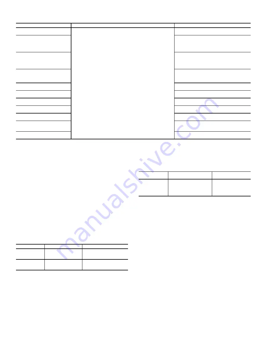
Table 29 — Slave Chiller Configuration in Series Applications
NOTES:
1. If pump control is configured to OFF (Master), then LAG UNIT (Slave) PUMP
SELECT (page 3 of the Master/Slave Config menu) = 1. If pump control is
set to any other value, then LAG UNIT (Slave) PUMP SELECT = 0. This con-
figuration must be set consistently for both master and slave chillers.
2. For Master/Slave Series Chiller Application, Master Chiller should always be
downstream of Slave.
DUAL CHILLER PUMP CONTROL FOR SERIES
CHILLER APPLICATIONS
Pump control for series chiller applications is controlled by the
master chiller only. The control of the slave chiller is directed
through commands transmitted by the master chiller. The slave
chiller has no action in master/slave operations. The slave
chiller only verifies that CCN communication with the master
chiller is present. See the Dual Chiller Sequence of Operation
section on page 55. Figure 36 shows a typical pump arrange-
ment for dual chiller series applications.
Ramp Loading
The Ramp Loading function limits the rate of change of the leav-
ing fluid temperature. The minimum compressor speed is calculat-
ed based on saturated condensing temperature and saturated suc-
tion temperature. To enable the Ramp Loading sequence:
Temperature Reset
The temperature reset function will determine the cooling con-
trol point. This control point is the active set point adjusted
with the current reset value:
Control Point = Se Reset
The purpose of this reset value is to decrease the required ca-
pacity if it is allowed by unit load operating conditions. When
a non-zero temperature reset is applied, the chiller controls to
the new control point instead of the set point. The type of tem-
perature reset is configured with the Cooling Reset Select vari-
able. Four types of temperature reset are available: Outdoor Air
Temperature, Return Water Reset (Delta T), 4 to 20mA control,
and Space Temperature control:
Under normal operation, the chiller will maintain a constant
entering or leaving fluid temperature, based on the configura-
tion, approximately equal to the chilled fluid set point. As the
evaporator load varies, the evaporator fluid temperature differ-
ence will change in proportion to the load. For example, if the
chiller was selected for an entering to leaving water tempera-
ture difference of 10°F (5.5°C) at full load, at 50% load the
temperature difference would be 5°F (2.2°C). See Fig. 37. Be-
cause the change in temperature through the evaporator is a
measure of the building load, the temperature difference reset
is the average building load. Usually the chiller size and fluid
temperature set point are selected based on a full load condi-
tion. At part load, the fluid temperature set point may be lower
than required. When the fluid temperature is allowed to in-
crease at part load, the efficiency of the machine will increase.
The chiller can also be set for return water temperature control.
See Fig. 38.
Other indirect means of estimating building load and con-
trolling temperature reset are also available and are discussed
below.
To verify that reset is functioning correctly, subtract the Cur-
rent Setpoint (
Main Menu
General Parameters
Current
Setpoint
) from the Control Point (
Main Menu
General Pa-
rameters
Control Point
) to determine the degrees reset.
DISPLAY NAME
PATH
VALUE
Master/Slave Select
Main Menu
Configuration Menu
Master/Slave Config
2 (Slave)
Default: 0 (Disable)
Master Control Type
1=Local Control
2=Remote Control
3=CCN Control
Default: 1(Local)
Configure for proper control type.
Slave Address
Must be set to the Slave Chiller’s address.
The master and slave chiller must have
different addresses and be on the same
Bus Number
Default: 2
Lead Lag Select
0 (Master Always Leads)
1 (Lag Once Failed Only)
2 (Lead/Lag Runtime Select)
Default: 0 (Master Always Leads)
Lead/Lag Balance Delta
Range: 40 to 400 hours
Default: 168 hours
Lead/Lag Start Timer
Range: 2 to 30 minutes
Default: 10 minutes
Lead Pulldown Time
Range: 0 to 60 minutes
Default: 0 minutes
Start If Error Higher
Range: 3.0 to 18°F (1.7 to 10.0°C)
Default: 4.0°F (2.2°C)
Lag Minimum Running Time
Range: 0 to 150 minutes
Default: 0 minutes
Lag Unit Pump Control
0 (Stop If Unit Stops)
1 (Run If Unit Stops)
Default: 0 (Stop If Unit Stops)
Chiller In Series
Yes (In Series)
Default: No
DISPLAY NAME
PATH
VALUE
Ramp Loading
Enable
Main Menu
Configuration Menu
General Configuration
Yes
Cooling Ramp
Loading
Main Menu
Setpoint Table
Range: 0.2 to 2.0°F/min (0.1 to
1.1°C/min)
Default: 1.0°F/min (0.5°C/min)
DISPLAY
NAME
PATH
VALUE
Cooling Reset
Select
Main Menu
Configuration Menu
Reset Configuration
0 = None
1 = OAT
2 = Delta T
3 = 4 to 20 mA Control
4 = Space Temp
Summary of Contents for AquaForce 30XV140
Page 79: ...79 Fig 76 VFD Communication Wiring Compressor A B Fan VFD A1 A2 B1 B2...
Page 228: ...228 Fig 90 30XV Typical Field Wiring Schematic cont...
Page 229: ...229 Fig 91 30XV Standard Tier 140 275 All Voltages Power Schematic NOTE See Legend on page 226...
Page 230: ...230 Fig 92 30XV Standard Tier 300 325 All Voltages Power Schematic NOTE See Legend on page 226...
Page 240: ...240 Fig 99 30XV Communication Wiring...
Page 241: ...241 Fig 100 30XV 115V Control Wiring All Tonnages All Voltages...
Page 242: ...242 Fig 101 30XV 24V Control Wiring 30XV140 325 All Voltages...
Page 243: ...243 Fig 101 30XV 24V Control Wiring 30XV140 325 All Voltages cont...
Page 244: ...244 Fig 102 30XV 24V Control Wiring 30XV350 500 All Voltages...
Page 245: ...245 Fig 102 30XV 24V Control Wiring 30XV350 500 All Voltages cont...
Page 246: ...246 Fig 103 Component Arrangement Diagram for 30XV140 325...
Page 247: ...247 Fig 103 Component Arrangement Diagram for 30XV140 325 cont...
Page 248: ...248 Fig 104 Component Arrangement Diagram for 30XV350 500...
Page 337: ...337 APPENDIX J FACTORY SUPPLIED PUMPS cont Fig L System Information...
Page 338: ...338 APPENDIX J FACTORY SUPPLIED PUMPS cont Fig M Unit and Language Settings...
Page 341: ...341 APPENDIX J FACTORY SUPPLIED PUMPS cont Fig P Data Input 2...
Page 342: ...342 APPENDIX J FACTORY SUPPLIED PUMPS cont Fig Q Data Input 3...
Page 347: ...347 APPENDIX J FACTORY SUPPLIED PUMPS cont Fig U Pump Wiring Diagram...


