


334
APPENDIX I — CARRIER CONTROLLER WEB AND NETWORK INTERFACE PARAMETERS (cont)
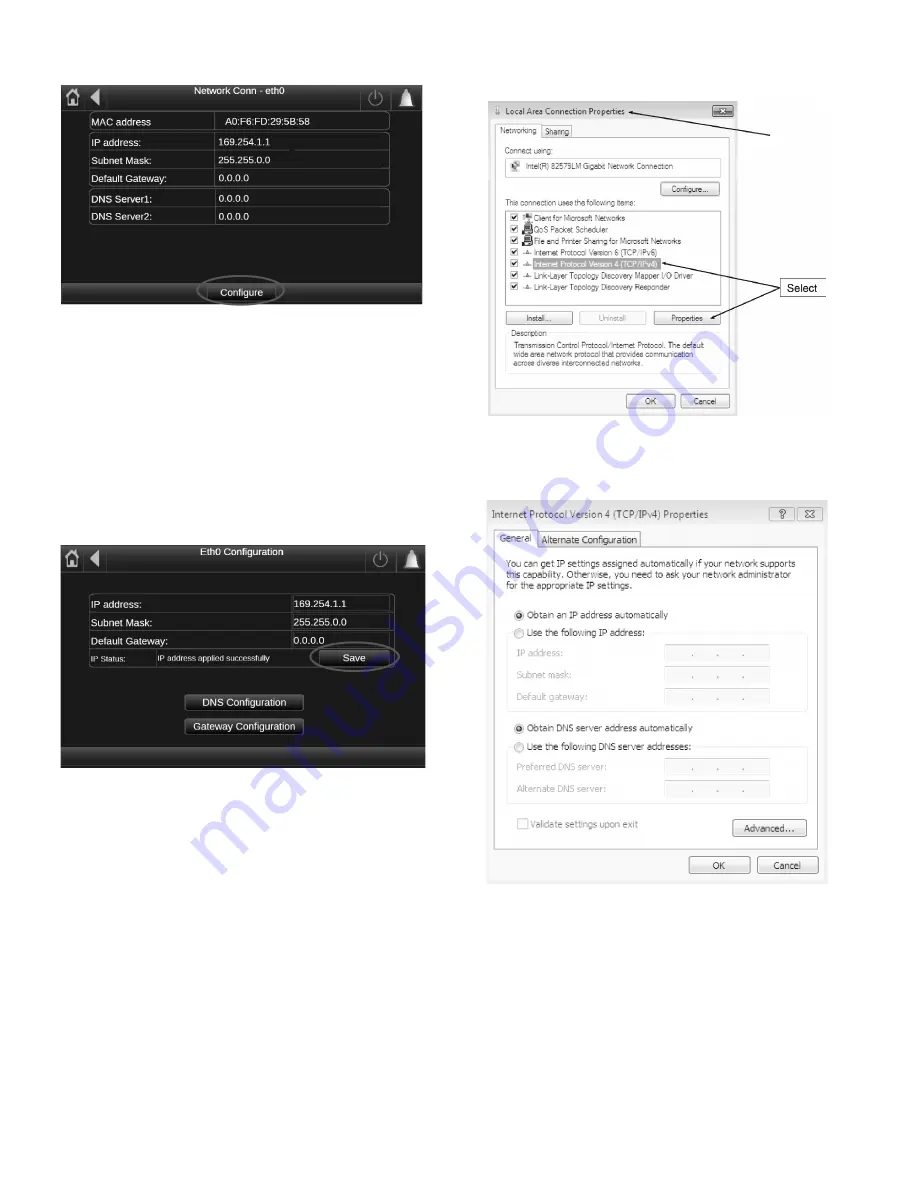
Fig. F — Network Connection Screen — Configure
Network Settings
Request an IP address, subnet mask, and default gateway from
the system administrator before connecting the unit to the local
Ethernet network. The NETWORK MENU allows the user to
define network parameters, including TCP/IP address.
1. To access and change the network parameters, select the
CONFIGURE button shown in Fig. F. This changes the
fields to editable fields and allows the selection of each field,
which can then be changed using the popup keyboard once
the field is selected. Once all of the network parameters have
been correctly entered select the SAVE button as shown in
Fig. G — Network Connection Screen — Save
2. For DNS configuration and Gateway configuration, select
the corresponding buttons as shown in Fig. G and enter the
appropriate information.
Once this is complete, the setup of the Carrier Controller
controller is complete. The computer or network that the
Carrier Controller controller is being connected to may need
to have some settings changed in order to communicate be-
tween them. See the next section.
ETHERNET/IP CONNECTION
If the unit is point-to-point to a PC and the unit is energized, it
may be necessary to check the Ethernet connection and/or con-
figure the PC network board. Refer to the following instruc-
tions to verify PC settings and connection to the Carrier Con-
troller controller.
To verify the unit’s IP address, perform the following steps:
1. From the computer connected to the controller, go to Local
Area Connection Properties and select Internet Protocol
(TCP/IP). See Fig. H.
Fig. H — Local Area Connection Properties Screen
2. Once the Properties button is selected the Internet Protocol
Properties Window opens. See Fig. I.
Fig. I — Internet Protocol Properties Screen
3. The IP address of the Carrier Controller controller must have
matching system and subsystem fields in order for the two to
communicate. In addition the last part of the IP address must
be unique for both on the network.
For example, Carrier Controller IP address: 172.30.101.11
and the PC address: 172.30.101.182.
In this example 172.30 corresponds to the network and 101
corresponds to the subsystem and they must match. The last
part of the IP address, 11 and 182, must be unique on the net-
work.
4. Confirm that the Carrier Controller IP address and the PC IP
address meets the above criteria and select OK on the PC.
Summary of Contents for AquaForce 30XV140
Page 79: ...79 Fig 76 VFD Communication Wiring Compressor A B Fan VFD A1 A2 B1 B2...
Page 228: ...228 Fig 90 30XV Typical Field Wiring Schematic cont...
Page 229: ...229 Fig 91 30XV Standard Tier 140 275 All Voltages Power Schematic NOTE See Legend on page 226...
Page 230: ...230 Fig 92 30XV Standard Tier 300 325 All Voltages Power Schematic NOTE See Legend on page 226...
Page 240: ...240 Fig 99 30XV Communication Wiring...
Page 241: ...241 Fig 100 30XV 115V Control Wiring All Tonnages All Voltages...
Page 242: ...242 Fig 101 30XV 24V Control Wiring 30XV140 325 All Voltages...
Page 243: ...243 Fig 101 30XV 24V Control Wiring 30XV140 325 All Voltages cont...
Page 244: ...244 Fig 102 30XV 24V Control Wiring 30XV350 500 All Voltages...
Page 245: ...245 Fig 102 30XV 24V Control Wiring 30XV350 500 All Voltages cont...
Page 246: ...246 Fig 103 Component Arrangement Diagram for 30XV140 325...
Page 247: ...247 Fig 103 Component Arrangement Diagram for 30XV140 325 cont...
Page 248: ...248 Fig 104 Component Arrangement Diagram for 30XV350 500...
Page 337: ...337 APPENDIX J FACTORY SUPPLIED PUMPS cont Fig L System Information...
Page 338: ...338 APPENDIX J FACTORY SUPPLIED PUMPS cont Fig M Unit and Language Settings...
Page 341: ...341 APPENDIX J FACTORY SUPPLIED PUMPS cont Fig P Data Input 2...
Page 342: ...342 APPENDIX J FACTORY SUPPLIED PUMPS cont Fig Q Data Input 3...
Page 347: ...347 APPENDIX J FACTORY SUPPLIED PUMPS cont Fig U Pump Wiring Diagram...


