


20
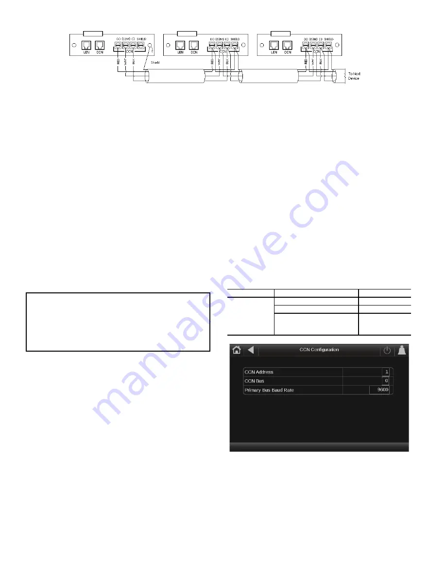
Fig. 22 — Carrier Controller CCN Communication Wiring
When connecting to a CCN communication bus, it is important
that a color-coding scheme be used for the entire network to
simplify the installation. It is recommended that red be used for
the signal positive, black for the signal negative, and white for
the signal ground. Use a similar scheme for cables containing
different colored wires.
At each system element, the shields of its communication bus
cables must be tied together. If the communication bus is entirely
within one building, the resulting continuous shield must be con-
nected to a ground at one point only. If the communication bus
cable exits from one building and enters another, the shields
must be connected to grounds at the lightning suppressor in each
building where the cable enters or exits the building (one point
per building only). To connect the unit to the network:
1. Turn off power to the control box.
2. Cut the CCN wire and strip the ends of the red (+), white
(ground), and black (–) conductors. (Substitute appropriate
colors for different colored cables.)
3. Connect the red wire to (+) terminal on TB3 of the plug, the
white wire to COM terminal, and the black wire to the (–)
terminal.
4. The RJ14 CCN connector on TB3 can also be used, but is
only intended for temporary connection (for example, a lap-
top computer running Network Service Tool).
External Sensor Wiring
External sensors, such as a Space Temperature Sensor, must be
wired to the unit, if values are not communicated. The wiring
should be CM or CMP rated depending on the application.
Wiring is field supplied and installed. For wiring runs of less
than 100 feet (30.5 m), 2-conductor, twisted pair, unshielded
wire is acceptable. For wiring runs of 100 feet (30.5 m) or
more, 2-conductor, twisted pair, shielded wire is recommend-
ed. For noise consideration, sensor wiring must be separate and
not run in parallel with other wiring.
NOTE: Conductors and drain wire must be 20 AWG stranded,
tinned copper. Individual conductors must be insulated with
PVC, PVC/nylon, vinyl, Teflon, or polyethylene. An alumi-
num/polyester 100% foil shield and an outer jacket of PVC,
PVC/nylon, chrome vinyl, or Teflon with a minimum operating
temperature range of –20°C to 60°C is required. High tempera-
ture applications may require a higher temperature range. Ple-
num applications will require plenum rated cable. Cable volt-
age requirements must match the application.
Remote Alarm and Alert Relays
The 30XV chiller can be equipped with remote alert and remote
alarm annunciator contacts. Both relays connected to these con-
tacts must be rated for a maximum power draw of 10 va sealed,
25 va inrush at 24 volts.
The remote alarm annunciator relay, indicating that one circuit
or the complete unit has been shut down, can be connected to
TB5-12 and TB5-21. Refer to unit wiring diagrams. For the re-
mote alert annunciator relay, indicating that an alert is active but
neither circuit is shut down, a field-supplied and installed relay
must be connected between TB6-18 and TB6-26. The Energy
Management Module is required for this feature. The unit con-
figuration must have the Energy Management Module enabled
(
Main Menu
Configuration Menu
Factory Parameter
)
set EMM to
YES
(1).
CONFIGURATION (SOFTWARE)
Carrier Controller Operation Configuration Tables
The Carrier Controller control system can be configured for a
range of operating conditions and equipment arrangements.
The following parameters should be configured based on
unique system layout and operating requirements.
The system parameters may be configured through the Carrier
Controller interface or remotely through the CCN. Table 13 shows
the Carrier Controller configuration required to access the unit on
the CCN. Figure 23 shows the CCN configuration screen.
Table 13 — Carrier Controller Identification
Configuration Table
Fig. 23 — CCN Configuration Screen
Carrier Controller Menu Tables
Carrier Controller operation is controlled by configuration in-
formation entered in the configuration tables listed in Tables
14-18. Access to different parameters may be available to all
users (BASIC) or password-protected (ADVANCED USER,
SERVICE, FACTORY). See Appendix A for detailed descrip-
tions of all control tables and parameters.
IMPORTANT: A shorted CCN bus cable will prevent
some routines from running and may prevent the unit
from starting. If abnormal conditions occur, disconnect
the CCN bus. If conditions return to normal, check the
CCN connector and cable. Run new cable if necessary. A
short in one section of the bus can cause problems with
all system elements on the bus.
PATH
DISPLAY NAME
VALUE
Main Menu
Configuration
Menu
HMI Configura-
tion Menu
CCN
Configuration
Menu
CCN Address
Default=1
CCN Bus
Default=0
Primary Bus Baud Rate
Default=9600
Summary of Contents for AquaForce 30XV140
Page 79: ...79 Fig 76 VFD Communication Wiring Compressor A B Fan VFD A1 A2 B1 B2...
Page 228: ...228 Fig 90 30XV Typical Field Wiring Schematic cont...
Page 229: ...229 Fig 91 30XV Standard Tier 140 275 All Voltages Power Schematic NOTE See Legend on page 226...
Page 230: ...230 Fig 92 30XV Standard Tier 300 325 All Voltages Power Schematic NOTE See Legend on page 226...
Page 240: ...240 Fig 99 30XV Communication Wiring...
Page 241: ...241 Fig 100 30XV 115V Control Wiring All Tonnages All Voltages...
Page 242: ...242 Fig 101 30XV 24V Control Wiring 30XV140 325 All Voltages...
Page 243: ...243 Fig 101 30XV 24V Control Wiring 30XV140 325 All Voltages cont...
Page 244: ...244 Fig 102 30XV 24V Control Wiring 30XV350 500 All Voltages...
Page 245: ...245 Fig 102 30XV 24V Control Wiring 30XV350 500 All Voltages cont...
Page 246: ...246 Fig 103 Component Arrangement Diagram for 30XV140 325...
Page 247: ...247 Fig 103 Component Arrangement Diagram for 30XV140 325 cont...
Page 248: ...248 Fig 104 Component Arrangement Diagram for 30XV350 500...
Page 337: ...337 APPENDIX J FACTORY SUPPLIED PUMPS cont Fig L System Information...
Page 338: ...338 APPENDIX J FACTORY SUPPLIED PUMPS cont Fig M Unit and Language Settings...
Page 341: ...341 APPENDIX J FACTORY SUPPLIED PUMPS cont Fig P Data Input 2...
Page 342: ...342 APPENDIX J FACTORY SUPPLIED PUMPS cont Fig Q Data Input 3...
Page 347: ...347 APPENDIX J FACTORY SUPPLIED PUMPS cont Fig U Pump Wiring Diagram...


