23
Software Configuration
See the 19MV with PIC6 Controls Operation and Troubleshoot-
ing manual for instructions on using the PIC6 interface to con-
figure the 19MV unit. As the unit is configured, all configuration
settings should be written down. A log, such as the one shown
starting on page CL-1, provides a list for configuration values.
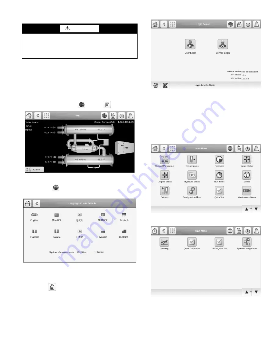
HOME SCREEN
The home screen is the first screen shown after switching the unit
on. See Fig. 19. Note the Globe
and Lock
icons.
Fig. 19 — Home Screen
The Globe icon
on the Home screen allows access to lan-
guage and measurement settings. See Fig. 20.
Fig. 20 — Language and Units Selection Screen
NOTE: The flags shown are not all supported. Contact chiller
marketing to learn about current language status.
The Lock icon
on the Home screen allows access to the pass-
word menu and displays current software version. See Fig. 21.
Fig. 21 — Login Screen
CHANGE THE SET POINTS
To access the set point screen, press the lock icon on the Main
Menu. In the User Login menu, enter the password (default
USER password = 1111), and click accept. The screen will then
default back to the home screen. See Fig. 19. The Service Login
access is reserved for access to equipment service tables.
The Main Menu screen is displayed. See Fig. 22 and 23. Press the
Setpoint Table icon.
Fig. 22 — Main Menu, Page 1
Fig. 23 — Main Menu, Page 2
The Setpoint screen is displayed. See Fig. 24. Set the base demand
limit, and either the LCW set point or the ECW set point. To set a
value, press the appropriate set point, enter the value, and press
OK. For more information, see the PIC6 Control User Manual.
WARNING
Do not operate the chiller before the control configurations
have been checked and a Calibration and Control Test has
been satisfactorily completed. Protection by safety controls
cannot be assumed until all control configurations have been
confirmed.
Summary of Contents for AquaEdge 19MV
Page 49: ...49 Fig 46 SIOB...
Page 50: ...50 Fig 47 IOB2...
Page 51: ...51 Fig 48 19MV Auxiliary Controls Wiring...


