6
−
6
T-364
o. Place the new Teflon seals at the compressor suc-
tion and discharge ports as well as the O
−
rings at the
unloader and economizer line connection ports.
Hand tighten all four connections.
p. Torque the four base
−
mounting screws to 6.2 mkg
(45 ft
−
lbs).
q. Torque the compressor ports / connections to:
Service Valve / Connection
Torque Value
Suction and Discharge
Rotalocks
108.5 to 135.5 Nm
(80 to 100 ft
−
lbs.)
Unloader connection
24.5 to 27 Nm
(18 to 20 ft
−
lbs.)
Economized connection
32.5 to 35 Nm
(24 to 26 ft
−
lbs.)
r. Connect (butt
−
splice and heat shrink) the new com-
pressor dome temperature sensor with the old
sensor wires removed in step h. Wire
−
tie any loose
wiring as appropriate.
s. Evacuate the compressor to 1000 microns if the unit
was pumped down before the replaced compressor
was removed. Otherwise, evacuate the complete
unit and charge it with R
−
134a refrigerant (see Sec-
t. Open the compressor terminal cover and connect
the compressor power cable following the steps be-
low:
1. Liberally coat the orange gasket surfaces with the
Krytox lubricant.
2. Install the orange gasket part onto the com-
pressor fusite with the grooved or threaded side
out. Ensure that the gasket is seated onto the fus-
ite base.
3. Coat the inside of the power plug (female) con-
nector pins with the Krytox lubricant, and insert the
plug onto the compressor terminal connections.
Make sure, the orange gasket has bottomed out
onto the fusite and it fits securely onto the terminal
pins while fully inserted into the orange plug.
4. Connect the green ground wire to the grounding
tab located inside the terminal box of the com-
pressor using the self
−
tapping grounding screw.
Close the compressor terminal box using the ter-
minal cover removed in step t.
u. Backseat all service valves, connect the power to the
unit and run it for at least 20 minutes.
v. Perform a leak check of the system.
6.9 HIGH PRESSURE SWITCH
6.9.1 Checking High Pressure Switch
WARNING
Do not use a nitrogen cylinder without a
pressure regulator.
NOTE
The high pressure switch is non-adjustable.
a. Remove switch as outlined in paragraph 6.9.2.
b. Connect ohmmeter or continuity light across switch
terminals. Ohm meter will indicate no resistance or
continuity light will be illuminated if the switch closed
after relieving compressor pressure.
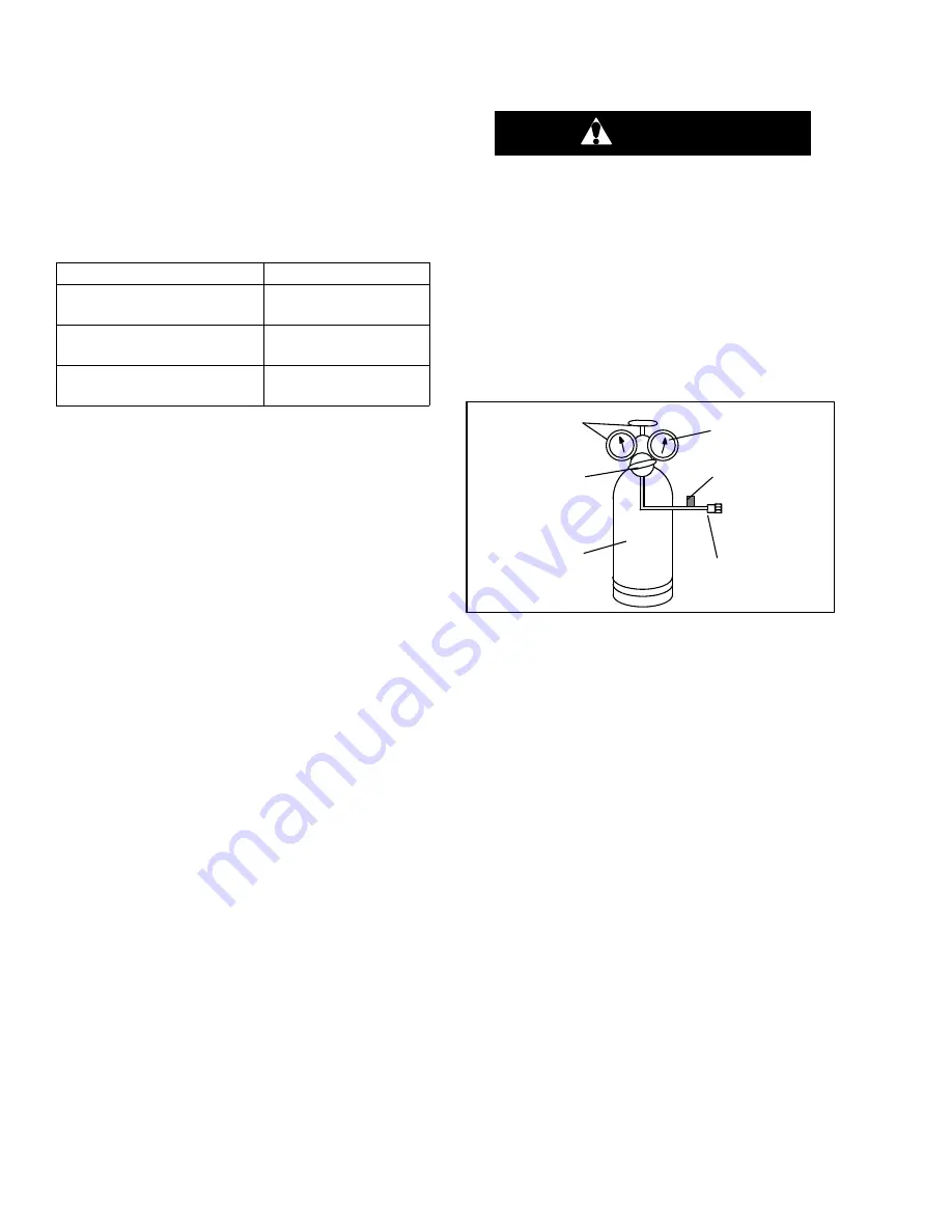
c. Connect hose to a cylinder of dry nitrogen. (See
1
2
3
4
5
6
1. Cylinder Valve
and Gauge
2. Pressure Regulator
3. Nitrogen Cylinder
4. Pressure Gauge
(0 to 36 kg/cm
2
=
0 to 400 psig)
5. Bleed-Off Valve
6. 1/4 inch Connection
Figure 6
−
6 High Pressure Switch Testing
d. Set nitrogen pressure regulator at 26.4 kg/cm
2
(375
psig) with bleed-off valve closed.
e. Close valve on cylinder and open bleed-off valve.
f. Open cylinder valve. Slowly close bleed-off valve to
increase pressure on switch. The switch should open
at a static pressure up to 25 kg/cm
2
(350 psig). If a
light is used, the light will go out. If an ohmmeter is
used, the meter will indicate open circuit.
g. Slowly open bleed-off valve to decrease the pressure.
The switch should close at 18 kg/cm
2
(250 psig).
6.9.2 Replacing High Pressure Switch
a. Remove the refrigerant charge.
b. Disconnect wiring from defective switch. The high
pressure switch is located on the discharge connec-
tion or line and is removed by turning counterclock-
wise.
c. Install a new high pressure switch after verifying
switch settings.
d. Evacuate, dehydrate and recharge the system.
e. Start the unit, verify refrigeration charge and oil level.
Summary of Contents for 69NT40-561-201
Page 2: ......
Page 11: ......
Page 15: ......
Page 29: ......
Page 81: ......
Page 108: ...7 2 T 364 Based on Drawing 62 11753 Figure 7 2 SCHEMATIC DIAGRAM ...
Page 109: ...7 3 T 364 Based on Drawing 62 11753 Figure 7 3 UNIT WIRING DIAGRAM Sheet 1 of 2 ...
Page 110: ...7 4 T 364 Based on Drawing 62 11753 Figure 7 3 UNIT WIRING DIAGRAM Sheet 2 of 2 ...
Page 111: ......
Page 115: ......
Page 116: ......


