background image

15

The piping for the condensate drain and external trap can be com

-

pleted after the unit is in place. See Fig. 20.


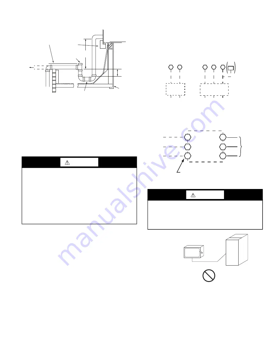
Fig. 20 — Condensate Drain Piping Details

All units must have an external trap for condensate drainage. In

-

stall  a  trap  at  least  4-in.  (102  mm)  deep  and  protect  against

freeze-up. If drain line is installed downstream from the external

trap, pitch the line away from the unit at 1-in. per 10 ft (25 mm in

3 m) of run. Do not use a pipe size smaller than the unit connec

-

tion (

3

/

4

-in.).

Step 11 — Make Electrical Connections

NOTE: Field-supplied wiring shall conform with the limitations

of minimum 63°F (33°C) rise.
FIELD POWER SUPPLY
If equipped with optional Powered Convenience Outlet: The pow

-

er source leads to the convenience outlet’s transformer primary are

not factory-connected. Installer must connect these leads accord

-

ing to required operation of the convenience outlet. If an always-

energized  convenience  outlet  operation  is  desired,  connect  the

source  leads  to  the  line  side  of  the  unit-mounted  disconnect.

(Check with local codes to ensure this method is  acceptable in

your area.) If a de-energize via unit disconnect switch operation of

the convenience outlet is desired, connect the source leads to the

load side of the unit disconnect. On a unit without a unit-mounted

disconnect, connect the source leads to compressor contactor C

and indoor fan terminal block (IFTB) pressure lugs with unit field

power leads.
Refer to Fig. 27 for power transformer connections and the dis

-

cussion on connecting the convenience outlet on page 16. Field

power wires are connected to the unit at line-side pressure lugs

on compressor contactor C and indoor fan contactor IFC (see

wiring diagram label for control box component arrangement) or

at  factory-installed  option  non-fused  disconnect  switch.  Max

wire size is #2 AWG (copper only, see Fig. 22). See Fig. 21 and

unit label diagram for field power wiring connections.

NOTE: TEST LEADS — Unit may be equipped with short leads

(pigtails) on the field line connection points on contactor C or op

-

tional disconnect switch. These leads are for factory run-test pur

-

poses  only;  remove  and  discard  before  connecting  field  power

wires to unit connection points. Make field power connections di

-

rectly to line connection pressure lugs only.


Fig. 21 — Power Wiring Connections


Fig. 22 — Disconnect Switch and Unit

UNITS  WITH  FACTORY-INSTALLED  NON-FUSED  DIS

-

CONNECT 
The factory-installed option non-fused disconnect (NFD) switch is

located in a weatherproof enclosure located under the main con

-

trol box. The manual switch handle and shaft are shipped in the

disconnect enclosure. Assemble the shaft and handle to the switch

at this point. Discard the factory test leads (see Fig. 21).

Connect field  power supply conductors to LINE side terminals

when the switch enclosure cover is removed to attach the handle.

WARNING

ELECTRIC SHOCK HAZARD

Failure to follow this warning could result in personal injury or

death.

Unit cabinet must have an uninterrupted, unbroken electrical

ground  to  minimize  the  possibility  of  personal  injury  if  an

electrical fault should occur. This ground may consist of elec

-

trical wire connected to unit ground lug in control compart

-

ment, or conduit approved for electrical ground when installed

in  accordance  with  NEC; ANSI/NFPA  70,  latest  edition  (in

Canada, Canadian Electrical Code CSA [Canadian Standards

Association] C22.1), and local electrical codes.

NOTE:  Trap should be deep enough to offset maximum unit static
 

difference. A 4-in. (102 mm) trap is recommended.  

MINIMUM PITCH
1˝ (25 mm) PER
1


(

3

 m) OF LINE 

BA

S

E RAIL

OPEN
VENT

TO ROOF
DRAIN

DRAIN PLUG

ROOF
CURB

S

EE NOTE

3

˝ (76 mm)

MIN

WARNING

FIRE HAZARD

Failure to follow this warning could result in personal injury,

death, or property damage.

Do not connect aluminum wire between disconnect switch and

unit. Use only copper wire.

Disconnect

per 

NEC

Disconnect

per 

NEC

20

8

/2

3

0-1-60

11

1

3

11

1

3

1

3

L1

L2

L

3

TB

C

C

IFC

or

(1-ph
 IFM)

20

8

/2

3

0-

3

-60

460-

3

-60

575-

3

-60

Units Without Non-Fused Disconnect Option

Units With Non-Fused Disconnect Option

2

4

6

1

3

5

L1

L2

L

3

Optional

Disconnect

S

witch

Disconnect factory test leads; discard.

Factory
Wiring

COPPER

WIRE ONLY

ELECTRIC

DI

S

CONNECT

S

WITCH

ALUMINUM

WIRE

Summary of Contents for 50KC04

Page 1: ...NTERFACE OVERVIEW SETUP AND CONFIGURATION ENTHALPY SETTINGS CHECKOUT TROUBLESHOOTING Control and Power Wiring Diagrams 34 Smoke Detectors 42 ADDITIONAL APPLICATION DATA PremierLink Controller Factory...

Page 2: ...unit rating plate Unit may have more than one power switch WARNING UNIT OPERATION AND SAFETY HAZARD Failure to follow this warning could cause personal injury death and or equipment damage R 410A refr...

Page 3: ...tric Relief F Enthalpy Economizer w Barometric Relief K 2 Position Damper U Temp Ultra Low Leak Economizer w Baro Relief W Enthalpy Ultra Low Leak Econo w Baro Relief Base unit controls 0 Electro mech...

Page 4: ...4 Fig 2 Unit Dimensional Drawing of Units Built On and After 4 15 19...

Page 5: ...5 Fig 3 Unit Dimensional Drawing of Units Built on and Prior to 4 15 19...

Page 6: ...6 Fig 4 Unit Corner Weights and Clearances...

Page 7: ...7 Fig 5 Base Rail Details...

Page 8: ...8 Fig 6 Thru the Base Charts...

Page 9: ...F CARRIER CORPORATION 1 DEC 2 DEC 3 DEC ANG MATERIAL AUTHORIZATION NUMBER TITLE 1041738 CURB ASY ROOF ENGINEERING MANUFACTURING 004 007 ENGINEERING REQUIREMENTS SIZE DRAWING NUMBER REV T 005 Y 002 DRA...

Page 10: ...ng refer to Step 10 for details 5 Rig and place unit 6 Install outdoor air hood 7 Install condensate line trap and piping 8 Make electrical connections 9 Install other accessories PAD MOUNTED INSTALLA...

Page 11: ...frame as a reference See Table 2 and Fig 9 for additional in formation Lifting holes are provided in base rails as shown in Fig 9 Refer to rigging instructions on unit Before setting the unit onto th...

Page 12: ...e covered by the tape used to secure the insulation to the basepan and are not easily seen See Fig 11 for position of the notches in the basepan Seals around duct openings must be tight Secure with sc...

Page 13: ...pan and remove Locate and cut the 2 plastic tie wraps securing the assembly to the damper See Fig 14 Be careful to not dam age any wiring or cut tie wraps securing any wiring Fig 14 Economizer Hood Pa...

Page 14: ...anels Only Relocate latch shipped inside the compressor compartment behind the hinged compressor door to location shown in Fig 18 after unit installation If the unit does not have hinged panels skip t...

Page 15: ...nnection points on contactor C or op tional disconnect switch These leads are for factory run test pur poses only remove and discard before connecting field power wires to unit connection points Make...

Page 16: ...abel diagram for power wir ing connections to the unit power terminal blocks and equipment ground Maximum wire size is 2 ga AWG copper only per pole on contactors Provide a ground fault and short circ...

Page 17: ...fuse lo cated in a utility box and mounted on a bracket behind the conve nience outlet access is through the unit s control box access panel See Fig 25 The primary leads to the convenience outlet tra...

Page 18: ...e the L bracket assembly from the unit 2 Remove connector plate assembly from the L bracket and discard the L bracket but retain the washer head screws and the gasket located between the L bracket and...

Page 19: ...ructions If the thermostat contains a logic circuit requiring 24 v power use a thermostat cable or equivalent single leads of different colors with minimum of seven leads If the thermostat does not re...

Page 20: ...ingle point box also includes a set of power taps and pigtails to complete the wiring between the single point box and the unit s main control box terminals Refer to the accessory heater and single po...

Page 21: ...trol To connect the Carrier humidistat HL38MG029 1 Route the humidistat 2 conductor cable field supplied through the hole provided in the unit corner post 2 Feed wires through the raceway built into t...

Page 22: ...iring Fig 42 Typical Rooftop Unit with Humidi MiZer Adaptive Dehumidification System with EDGE Pro Thermidistat Device Rc Rh W1 G Y2 C O W2 B Y1 OAT RRS SRTN HUM D1 D2 V Vg X C G W2 W1 Y2 Y1 R EDGE Pr...

Page 23: ...ce Provides status for normal operation setup parameters checkout tests and alarm and error conditions with a 2 line 16 character LCD display and four button keypad Electrical Rated Voltage 20 to 30 v...

Page 24: ...Sensor Input e g CO2 sensor IAQ COM COM Air Quality Sensor Common IAQ 24V 24 vac Air Quality Sensor 24 vac Source ACT 2 10 2 10 vdc Damper Actuator Output 2 10 vdc ACT COM COM Damper Actuator Output C...

Page 25: ...220 Controller Navigation Buttons To use the keypad when working with Setpoints System and Ad vanced Settings Checkout tests andAlarms 1 Navigate to the desired menu 2 Press the Enter button to displa...

Page 26: ...lled system The setup process uses a hierarchical menu structure that is easy to use Press the and arrow buttons to move forward and back ward through the menus and press the button to select and conf...

Page 27: ...nd displays measured discharge temperature Displays _ _ _F if sensor sends invalid value if not connected short or out of range OA TEMP _ _ _ F or _ _ _ C 40 F to 140 F 40 C to 60 C OUTSIDE AIR TEMP D...

Page 28: ...isplays only if CO2 sensor is connected Set point for Demand Controlled Ventilation of space Above the set point the OA dampers will modulate open to bring in additional OA to maintain a space ppm lev...

Page 29: ...ON Damper position when freeze protection is active closed or MIN POS CO2 ZERO 0ppm 0 to 500 ppm Increment by 10 CO2 ppm level to match CO2 sensor start level CO2 SPAN 2000ppm 1000 to 3000 ppm Increme...

Page 30: ...nge or become disconnected check wiring then replace sensor if the alarm continues OA SYLK T ERR N A N A OUTSIDE AIR S BUS SENSOR ERROR Outdoor air enthalpy sensor has failed or become disconnected ch...

Page 31: ...or 2 Speed unit operation EQUIPMENT CONV AUX2 I W FAN SPEED 2SPEED For damper minimum position settings and checkout menu read ings see Table 8 For dry bulb operation with or without DCV see Tables 9...

Page 32: ...High 24 v On 24 v On VENTMIN to VENTMAX Closed Yes Off Off High 0 v Off 0 v Off VENTMIN to VENTMAX Closed On Off High 0 v Off 0 v Off VENTMIN to Full Open Closed to Full Open On On High 24 v On 0 v Of...

Page 33: ...sion of the software appears on the first line and the second line will be blank Power Loss Outage or Brownout All set points and advanced settings are restored after any power loss or interruption NO...

Page 34: ...g Alarms Once the alarm has been identified and the cause has been re moved e g replaced faulty sensor the alarm can be cleared from the display To clear an alarm perform the following 1 Navigate to t...

Page 35: ...35 Fig 49 Electro Mechanical Control Wiring Diagram...

Page 36: ...36 Fig 50 Electro Mechanical Control Wiring Diagram with Humidi MiZer System...

Page 37: ...37 Fig 51 Electro Mechanical Power Wiring...

Page 38: ...38 Fig 52 PremierLink Wiring Schematic...

Page 39: ...39 Fig 53 PremierLink Wiring Schematic with Humidi MiZer System...

Page 40: ...40 Fig 54 RTU Open System Control Wiring Diagram...

Page 41: ...41 Fig 55 RTU Open System Control Wiring Diagram with Humidi MiZer System...

Page 42: ...See Fig 57 Step 3 4 Connect the flexible tube on the sampling inlet to the sam pling tube on the basepan ADDITIONAL APPLICATION DATA Refer to the application data document Factory Installed Smoke Dete...

Page 43: ...CO2 sensor DDC interface PremierLink Louvered hail guard Motormaster head pressure controls Phase monitor control Refer to separate installation instructions for information on in stalling these acces...

Page 44: ...and Maintenance Instructions Pre Start and Start Up This completes the mechanical installation of the unit Refer to the unit s Service Manual for detailed Pre Start and Start Up instruc tions Downloa...

Page 45: ...45 Fig 61 50KC A B Sizes 04 05 Metering Devices ACCUTROL NOTE Each feeder tube in the liquid header has a metering device...

Page 46: ...46 Fig 62 50KC A B Sizes 06 Dual Metering Devices ACCUTROL ACCURATER NOTE Each feeder tube in the liquid header has a metering device...

Page 47: ...47 Fig 63 TXV Metering Device Position in Reheat Coil Typical Diagram for Sizes 04 06 TXV...

Page 48: ......

Page 49: ......

Page 50: ...o discontinue or change at any time specifications or designs without notice and without incurring obligations Catalog No 04 53500239 01 Printed in U S A Form 50KC 4 6 03SI Pg 50 3 2020 Replaces 50KC...

Page 51: ...location in housing orifice and verify setscrew is tight Y N _____ Verify that fan sheaves are aligned and belts are properly tensioned Y N _____ Verify that scroll compressors are rotating in the co...

Page 52: ...fan motor as condenser coil warms Y N _____ 4 Check unit charge per charging chart Y N _____ Jumper 32L Motormaster temperature sensor during this check Remove jumper when complete 5 Switch unit to hi...

Reviews: