background image

20

FIELD CONTROL WIRING
The 50HC unit requires an external temperature control device.

This device can be a thermostat (field-supplied) or a Premier-

Link™ controller (available as factory-installed option or as field-

installed accessory, for use on a Carrier Comfort Network

®

 or as a

stand-alone control) or the RTU Open Controller for Building

Management Systems using non-CCN protocols (RTU Open is

available as a factory-installed option only).
THERMOSTAT
Select a Carrier-approved accessory thermostat. When electric

heat is installed in the 50HC unit, the thermostat must be capable

of energizing the G terminal (to energize the Indoor Fan Contac-

tor) whenever there is a space call for heat (energizing the W1 ter-

minal). The accessory thermostats listed on the unit price pages

can provide this signal but they are not configured to enable this

signal as shipped.
Install the accessory thermostat according to installation instruc-

tions included with the accessory.
Locate the thermostat accessory on a solid wall in the conditioned

space to sense average temperature in accordance with the ther-

mostat installation instructions.
If the thermostat contains a logic circuit requiring 24-v power, use

a thermostat cable or equivalent single leads of different colors

with minimum of seven leads. If the thermostat does not require a

24-v source (no “C” connection required), use a thermostat cable

or equivalent with minimum of six leads. See Fig. 35. Check the

thermostat installation instructions for additional features which

might require additional conductors in the cable.
For wire runs up to 50 ft. (15 m), use no. 18 AWG (American

Wire Gage) insulated wire [35°C (95°F) minimum]. For 50 to

75 ft. (15 to 23 m), use no. 16 AWG insulated wire [35°C (95°F)

minimum]. For over 75 ft. (23 m), use no. 14 AWG insulated wire

[35°C (95°F) minimum]. Wire sizes larger than no. 18 AWG can-

not be directly connected to the thermostat and will require a junc-

tion box and splice at the thermostat.

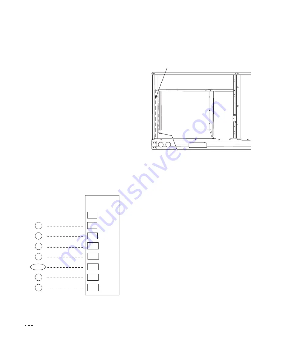
Fig. 35 — Low-Voltage Thermostat Connections

Thermostat Wiring, Units Without Thru-Base Connection Kit

Pass the thermostat control wires through the hole provided in the

corner post; then feed the wires through the raceway built into the

corner post to the control box. Pull the wires over to the terminal

strip on the upper-left corner of the Controls Connection Board.

See Fig. 36.
NOTE: If thru-the-bottom connections accessory is used, refer to

the accessory installation instructions for information on routing

power and control wiring.

Fig. 36 — Field Control Wiring Raceway

HEAT ANTICIPATOR SETTINGS
Set heat anticipator settings at 0.14 amp for the first stage and

0.14 amp for second-stage heating, when available.
ELECTRIC HEATERS
The 50HC units may be equipped with factory or field-installed

electric heaters. The heaters are modular in design, with heater

frames holding open coil resistance wires strung through ceramic

insulators, line-break limit switches and a control contactor. One

or two heater modules may be used in a unit.
Heater modules are installed in the compartment below the indoor

(supply) fan outlet. Access is through the indoor access panel.

Heater modules slide into the compartment on tracks along the

bottom of the heater opening. See Fig. 37-39.
Not all available heater modules may be used in every unit. Use

only those heater modules that are UL listed for use in a specific

size unit. Refer to the label on the unit cabinet for the list of ap-

proved heaters.
Unit heaters are marked with heater model numbers, but accessory

heaters are ordered as and shipped in cartons marked with a corre-

sponding heater sales package part number.
NOTE: The value in position 9 of the part number differs between

the sales package part number (value is 1) and a bare heater model

number (value is 0).

X

C

G

W2

R

C

W2

G

W1

O/B/Y2

Y2

W1

R

Y1

Y1

   Typical
Thermostat
Connections

T
H
E
R
M
O
S
T
A
T

(Note 1)

(Note 2)

(Note 3)

1.  Typical multi-function marking. Follow manufacturer’s configuration 

    instructions to select Y2.

2.  Y2 to Y2 connection required on single-stage cooling units when 

    integrated economizer function is desired

3.  W2 connection not required on units with single-stage heating.


Field Wiring

Central

Terminal

Board

Notes:

RACEWAY

HOLE IN END PANEL (HIDDEN)

Summary of Contents for 50HC Series

Page 1: ...ontrol Factory Option 45 PremierLink Factory Option 45 RTU Open Controller Factory Installed Option 45 Smoke Detectors 45 ADDITIONAL APPLICATION DATA CONTROLLER OPTIONS Step 12 Adjust Factory Installe...

Page 2: ...410A refrigerant systems operate at higher pressures than standard R 22 systems Do not use R 22 service equipment or components on R 410A refrigerant equipment WARNING PERSONAL INJURYAND ENVIRONMENTAL...

Page 3: ...d Diagnostic 1 PremierLink Controller 2 RTU Open Multi Protocol Controller 6 Electro mechanical w 2 speed fan and W7220 Economizer controller Can be used with W7220 EconoMi er X with Fault Detection a...

Page 4: ...4 Fig 2 50HC 04 06 Units Built On and After 4 15 2019...

Page 5: ...5 Fig 3 50HC 04 06 Units Built Prior to 4 15 2019...

Page 6: ...6 Fig 4 50HC 04 06 Corner Weights and Clearances...

Page 7: ...7 Fig 5 50HC 04 06 Base Rail Details...

Page 8: ...8 Fig 6 50HC 04 06 Thru the Base Charts...

Page 9: ...3 Rig and place unit 4 Convert unit to side duct connection arrangement 5 Install field fabricated ductwork at unit duct openings 6 Install outdoor air hood 7 Install condensate line trap and piping 8...

Page 10: ...ENGINEERING MANUFACTURING ENGINEERING REQUIREMENTS SIZE DRAWING NUMBER REV T 005 Y 002 DRAFTER CHECKER D 48TC400427 B WEIGHT MMC 06 17 11 SHEET 5 OF 5 SURFACE FINISH MFG PURCH MODEL INTERNAL USE ONLY...

Page 11: ...onto the curb recheck gasketing on curb POSITIONING ON CURB Position unit on roof curb so that the following clearances are maintained 1 4 in 6 4 mm clearance between the roof curb and the base rail i...

Page 12: ...atherproof all external ductwork joints and roof or build ing openings with counter flashing and mastic in accordance with applicable codes Do not cover or obscure visibility to the unit s informative...

Page 13: ...ith the unit will not be used and must be discarded Save the aluminum filter for use in the power exhaust hood assembly 1 The indoor coil access panel will be used as the top of the hood Remove the sc...

Page 14: ...ith the limitations of minimum 63 F 33 C rise FIELD POWER SUPPLY If equipped with optional powered convenience outlet the power source leads to the convenience outlet s transformer primary are not fac...

Page 15: ...nd shaft are shipped in the disconnect or HACR enclosure Assemble the shaft and handle to the switch at this point Discard the factory test leads see Fig 22 See Fig 21 Connect field power supply condu...

Page 16: ...he handle socket re install 3 hex screws on the NFD enclosure 12 Re install the unit front panel Fig 23 NFD Enclosure Location Fig 24 NFD Handle and Shaft Assembly Field Install the HACR Shaft and Han...

Page 17: ...Check all factory and field electrical connections for tightness CONVENIENCE OUTLETS Two types of convenience outlets are offered on 50HC models non powered and unit powered Both types provide a 125...

Page 18: ...let has a duty cycle limitation The transformer is intended to provide power on an intermittent basis for service tools lamps etc it is not intended to provide 15 amps loading for continuous duty load...

Page 19: ...side panel Remove one of the two knockouts located on the bottom left side of the unit control box Use this hole for the control conduit UNITS WITHOUT THRU BASE CONNECTIONS ELEC TRICAL CONNECTIONS 1 I...

Page 20: ...iring Units Without Thru Base Connection Kit Pass the thermostat control wires through the hole provided in the corner post then feed the wires through the raceway built into the corner post to the co...

Page 21: ...ig 40 Typical Single Point Installation Low Voltage Control Connections All units except size 06 575V Pull the low voltage control leads from the heater module s VIO and BRN two of each if two modules...

Page 22: ...may be a separate humidistat control contact closes on rise in space RH above control setpoint or a combination ther mostat humidistat control device such as Carrier s Edge Pro Thermidistat with isola...

Page 23: ...des the UL required clearance between high voltage and low voltage wiring 3 The Thermidistat has dry contacts at terminals D1 and D2 for dehumidification operation see Fig 46 The dry contacts must be...

Page 24: ...Humidi MiZer Adaptive Dehumidification System and Edge Pro Thermidistat Device Rc Rh W1 G Y2 C O W2 B Y1 OAT RRS SRTN HUM D1 D2 V Vg X C G W2 W1 Y2 Y1 R EDGE Pro THERMIDISTAT Unit CTB THERMOSTAT Conne...

Page 25: ...25 Fig 47 Electro Mechanical Control Wiring Diagram...

Page 26: ...26 Fig 48 Electro Mechanical Control Wiring Diagram with Humidi MiZer System...

Page 27: ...27 Fig 49 Electro Mechanical Control Power Wiring Diagram...

Page 28: ...28 Fig 50 ComfortLink Control Wiring Diagram 50HC 3 5 Ton Units NOTE See Fig 51 for all NOTE references in this wiring diagram...

Page 29: ...29 Fig 51 50HC ComfortLink Control with Humidistat Power Wiring Diagram 208 230V 460V 575V 3 Phase...

Page 30: ...30 Fig 52 50HC ComfortLink Control with Humidi MiZer System Power Wiring Diagram 208 230V 460V 575V 3 Phase...

Page 31: ...31 Fig 53 PremierLink Wiring Schematic...

Page 32: ...32 Fig 54 PremierLink Wiring Schematic with Humidi MiZer System...

Page 33: ...33 Fig 55 RTU Open System Control Wiring Diagram...

Page 34: ...34 Fig 56 RTU Open System Control Wiring Diagram with Humidi MiZer System...

Page 35: ...vides status for normal operation setup parameters checkout tests and alarm and error conditions with a 2 line 16 character LCD display and four button keypad Electrical Rated Voltage 20 to 30 vac RMS...

Page 36: ...Sensor Input e g CO2 sensor IAQ COM COM Air Quality Sensor Common IAQ 24V 24 vac Air Quality Sensor 24 vac Source ACT 2 10 2 10 vdc Damper Actuator Output 2 10 vdc ACT COM COM Damper Actuator Output C...

Page 37: ...20 Controller Navigation Buttons To use the keypad when working with Setpoints System and Ad vanced Settings Checkout tests and Alarms 1 Navigate to the desired menu 2 Press the Enter button to displa...

Page 38: ...OUT terminal COOL Y2 IN OFF ON OFF SECOND STAGE COOLING DEMAND Y2 IN Y2 I signal from space thermostat or unitary controller for second stage cooling ON 24 vac on terminal Y2 I OFF 0 vac on terminal Y...

Page 39: ...o as the Compressor lockout At or below the set point the Y1 O and Y2 O will not be energized on the controller DRYBLB SET 63 F 17 C 48 F to 80 F 9 C to 27 C increment by 1 degree OA DRY BULB TEMPERAT...

Page 40: ...he capacity of the RTU The value is found on the nameplate label for the specific unit AUX1 OUT NONE NONE ERV EXH2 SYS Select OUTPUT for AUX1 O relay NONE not configured output is not used ERV Energy...

Page 41: ...n damper to the full open position Exhaust fan contacts enable during the DAMPER OPEN test Make sure to pause in the mode to allow exhaust contacts to energize due to the delay in the system DAMPER CL...

Page 42: ...N A N A ACTUATOR ERROR Actuator has failed or become disconnected check for stall over voltage under voltage and actuator count Replace actuator if damper is movable and supply voltage is between 21 6...

Page 43: ...NTILATION DCV OUTSIDE AIR GOOD TO ECONOMIZE Y1 I Y2 I FAN SPEED Y1 O Y2 O OCCUPIED UNOCCUPIED Below CO2 set No Off Off High 0 v Off 0 v Off VENTMIN Closed On Off High 24 v On 0 v Off VENTMIN Closed On...

Page 44: ...gh 0 v Off 0 v Off VENTMIN to Full Open Closed to Full Open On On High 24 v On 0 v Off VENTMIN to Full Open Closed to Full Open Above CO2 set No Off Off High 0 v Off 0 v Off VENTMIN to VENTMAX Closed...

Page 45: ...ess the Menu Up button to end the test The Checkout tests can all be performed at the time of installation or at any time during the operation of the system as a test that the system is operable TROUB...

Page 46: ...let to the sam pling tube on the basepan ADDITIONAL APPLICATION DATA Refer to the application data document Factory Installed Smoke Detectors for Small and Medium Rooftop Units 2 to 25 Tons for discus...

Page 47: ...terface PremierLink Louvered hail guard Motormaster head pressure controls Phase monitor control EnergyX Recovery Ventilation ERV Refer to separate installation instructions for information on in stal...

Page 48: ...cpartners com TABLE 1 TABLE 2 BELT CROSS SECTION SMALLEST SHEAVE DIAMETER BELT DEFLECTION FORCE LBS UNNOTCHED BELTS NOTCHED BELTS USED NEW USED NEW A AX 3 0 3 6 3 7 5 5 4 1 6 1 3 8 4 8 4 5 6 8 5 0 7 4...

Page 49: ......

Page 50: ...o discontinue or change at any time specifications or designs without notice and without incurring obligations Catalog No 04 53500238 01 Printed in U S A Form 50HC 4 6 03SI Pg 50 12 19 Replaces 50HC 4...

Page 51: ...ns and terminals are tight Y N _____ Check that indoor air filters are clean and in place Y N _____ Check that outdoor air inlet screens are in place Y N _____ Verify that unit is level Y N _____ Chec...

Page 52: ...outlet or reheat coil _______________ F E Confirm correct rotation for compressor Y N _____ F Check for correct ramp up of outdoor fan motor as condenser coil warms Y N _____ 4 Check unit charge per c...

Reviews: