5 - AIR CONNECTIONS
Air quality:
Comfort units are not designed to control the humidity of outside
air. Fresh air handling must be provided by an independent
system in accordance with accepted engineering practice (see
CARRIER’s ranges of air handling units).
Warning
: on all models with plenums, all collars must be
connected. None must be capped, either at the supply or return
air.
Fresh air knockout
The fresh return air must be taken from air pretreated by an
air handling unit which complies with European regulation No.
1253/2014.
Under no circumstances may fresh air from outdoors be
connected directly to the unit.
Fitting and adjusting fresh air collars (accessory)
- Remove the washer from the pre-punched panel by
cutting the attachment points.
- Fasten the collar with or without controller using the 4
screws supplied.
- Either remove or leave on the shims needed to obtain the
desired flow rate. The flow rate ranges are given on the
label on the casing.
- 2 shims for minimum flow, 1 shim for medium flow, no
shims for maximum flow.
- The pressure difference must be between 50 and 100 Pa
in order to obtain the desired flow rate.
- Maintain the controller in the “BAS” (down) position.
6 - HYDRAULIC CONNECTIONS
The coils are fitted with a ‘female’ hydraulic connection, a turning
nut with a flat face (1/2” and 3/4” in diameter, depending on the
size) and an O ring (supplied with the unit), an air bleed valve
and a drain valve.
Water always flows into the bottom of the coil and exits at the
top.
To install a control valve with a flat face
(fig. 8)
:
l
Two-way valve:
screw the valve and gasket provided directly
on the hydraulic connections at the coil intake (at the bottom):
- 2-way valve, 2 pipe version (fig. 8a)
- 2-way valve, 4 pipe version (fig. 8b)
l
Three-way valve with integral bypass:
add the copper pipe
before fitting the valve:
4-way valve, 2 pipe version (fig. 8c)
4-way valve, 4 pipe version (fig. 8d), onto the coil cooling
connection.
Installation
l
To avoid damaging this coupling or the
CARRIER
valve, never tighten to more than
1.8 daN.m of torque. Use 2 spanners, one to
hold and the other to tighten, to ensure the
valve connection seal is maintained.
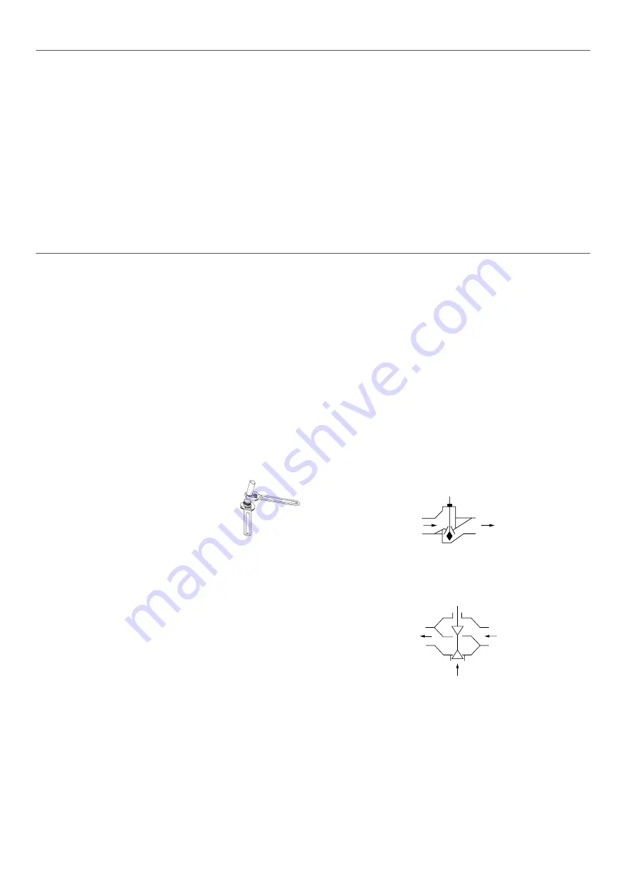
Always fit the valve in the right direction. The direction of flow for
these
CARRIER
valves should be
A
>
AB
(A being connected
to the coil and AB to the hydraulic network). The maximum
allowable differential pressure for our valves (open or closed) is
100 kPa.
CARRIER
recommends not exceeding 60 kPa.
Recommendations on hydraulic connections
The design of a hydraulic network is crucial to the correct
operation of the system. Drain valves should therefore be placed
at the appropriate points and in sufficient number. In addition,
strainers should be fitted, as well as drains at circuit high points,
balancing tees on each unit and, if necessary, discharge valves.
Pressure safety:
The installation must be protected against any risk of pressure
surges. Special care must be taken to protect against the risks
linked to expansion of the energy transfer fluid and to the total
hydrostatic pressure.
Filtration:
An efficient filtration system (recommended mesh size of 0.5
mm) should be fitted on the supply water and return water lines.
Flushing:
The system must be flushed completely and filled with treated water
to prevent the build-up of scale or sludge in the circuit. When flushing
the system, open the valve on the unit to prevent any sludge or scale
entering the coil:
l
Thermostatic valves: remove the servomotor to fit the cap,
which will cause pressure to be applied to the shaft, thereby
opening the passage, or request that the valve is opened by
the control.
A
AB
l
3-position modulating valves: if the power has not yet been
switched on, the valve will be open by default. If the control
has already been powered up, remove the servomotor to
release the rod and open the passage.
AB
A
B
Filling:
Drain the coils during system start-up.
12
Summary of Contents for 42NC
Page 2: ...2...
Page 5: ...1 2 3 4 5 6 7 8 9 10 11 12 3 a c a b 4 100 mm mini a b 5 6 5...
Page 6: ...7 a 8 b c 6...
Page 7: ...d 09 a 10 c b a d e 7...
Page 8: ...11 b a e c d a b c 12 a b 13 b 14 a c d e 8...
Page 9: ...b a b a 15 16 a 17 b c d 18 e 9...
Page 18: ...18...
Page 19: ...19...


