background image

2

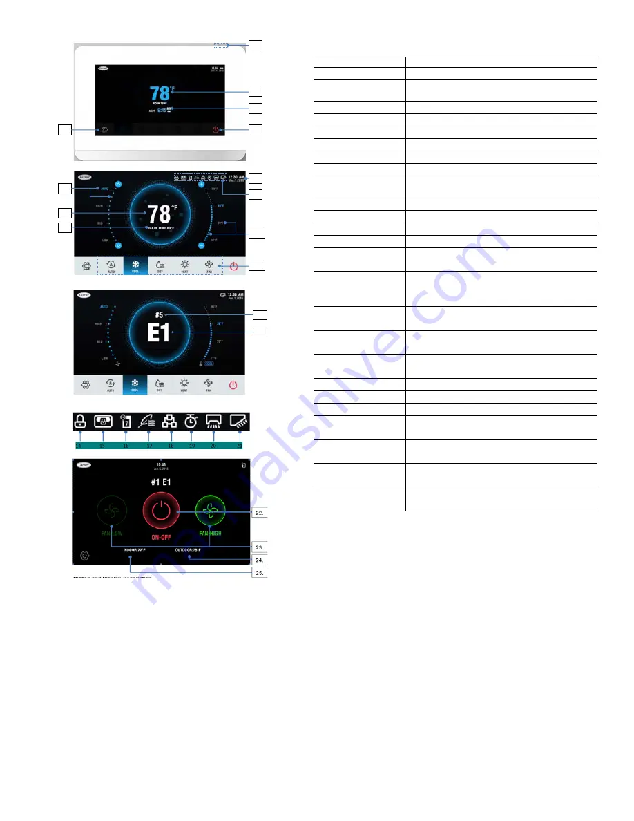
Fig. 1 — Touch Screen Wired Controller Icons

11. 

6.

8.

7.

9.

2.

10.

12. 

13. 

1.

2.

3.

5.

4.

ICON

DESCRIPTION

1. Screen ON/OFF icon

Turns the Screen on/off

2. Room temperature 

display

Display current room temperature

3. Scheduled time

Displays next scheduled event

4. Menu icon

Enters the menu

5. ON/OFF icon

Powers the IDU on/off

6. Date and Time

Displays the date and time

7. Fan speed settings

Sets and displays the current fan speed

8. Status bar

Displays setting items

9. Set temperature 

display

Displays the temperature setpoint

10. Temperature setpoint Adjusts temperature setpoint
11. Mode icon

Chooses mode

12. Error IDU Address

Displays address of IDU in error

13. Error codes

Displays error codes

14. Function locking 

indicator

Turns on when the wired controller locks the on/off function, 
mode, or temperature setting

15. Central controller 

locking indicator

Turns on when the central controller locks the IDU function 
and the wired controller cannot use the corresponding 
functions of the IDU 

16. Schedule

Turns on when the weekly schedule is available on the wired 
controller

17. Outside air unit 

symbol

Turns on when the wired controller is being used on a VRF 
outside air unit

18. Group control 

indicator

Turns on when the wired controller controls multiple IDUs 
(max 16 IDUs)

19. Override

Turns on when Override is enabled on the wired controller

20. Horizontal swing

Displays swing status when the IDU supports horizontal swing

21. Vertical swing

Displays swing status when the IDU supports vertical swing

22. DI/DO ON/OFF icon

Powers the DI/DO interface on/off (connected to a DI/DO 
interface)

23. DI/DO Fan speed 

setting

Sets and displays the current fan speed (connected to a DI/
DO interface)

24. Outdoor temperature 

display

Displays the current Outdoor temperature (connected to a 
DI/DO interface)

25. Indoor temperature 

display

Displays the current indoor temperature (connected to a DI/
DO interface)

Table 3 — Icon Descriptions

Summary of Contents for 40VM Series

Page 1: ...sult in severe personal injury or death WARNING signifies hazards that could result in personal injury or death CAUTION is used to identify unsafe practices Table 2 Wired Controller Accessory Usage NA...

Page 2: ...he central controller locks the IDU function and the wired controller cannot use the corresponding functions of the IDU 16 Schedule Turns on when the weekly schedule is available on the wired controll...

Page 3: ...3 DIMENSIONAL DRAWING 7 1 4 4 7 8 1 1 8 Front View Side View Rear View 2 1 4 3 1 8 Fig 2 Dimensions Note All dimensions are shown in inches...

Page 4: ...indoor units see Fig 4 2 Connect field provided 24VAC power to R and C terminals 1 Remove back cover from controller as shown in Figure 5 2 Cut a hole in the wall for the 2 wire bundles Run the wires...

Page 5: ...is turned on as shown in Figure 10 Touch the corresponding fan speed text or the icon to set the fan speed See Figure 12 Fig 8 Snap controller into place Push WALL Fig 9 Turn screen on Fig 10 On Off s...

Page 6: ...E AND TIME Used to configure date and time settings and corrections DAYLIGHT SAVINGS TIME Used to adjust the clock in observance of daylight savings time ROOM TEMP Used to set display room temperature...

Page 7: ...Reset to reset all the scheduled tasks Holiday settings 1 Touch the icon from the Setting Schedule screen Figure 20 to access Holiday settings Touch to create a new Holiday Touch Edit to adjust the ex...

Page 8: ...ose Daylight savings time on the Menu interface 2 Turn the Daylight savings time ON OFF 3 Touch the Edit icon 4 Slide the corresponding items to set the start date and end date respectively 5 Touch th...

Page 9: ...rds Touch the Delete icon to delete all the error messages It displays the unit address 0 63 for indoor unit and 128 for outdoor unit and the related error code An address is not displayed when the wi...

Page 10: ...tion setting on the Service interface Fig 35 Query Dry Contact Status Fig 36 Service Menu Password Entry Fig 37 Room temp location The room temperature location can be set to Indoor unit or Wired remo...

Page 11: ...below this setting Default setting is 68F Fig 43 Thermo Off Fan Speed This determines IDU fan behavior when the zone is satisfied thermo off for both heating and cooling mode For cooling mode the defa...

Page 12: ...tal Heat Aux Heat Status These settings are used when the IDU is controlling a field provided auxiliary heat source via its ACB interface contact output Turning Aux Heat Status on enables this functio...

Page 13: ...hedules room temperature display etc Reset setting 1 Choose Reset setting on the Service interface 2 Touch the Reset icon to reset 3 Touch the YES icon to confirm the operation Fig 52 Firmware Update...

Page 14: ...tic pressure of the DC fan 0 0 in WC default 1 0 04 in WC 2 0 08 in WC 3 0 12 in WC 4 0 16 in WC 5 0 20 in WC 6 0 24 in WC 7 0 28 in WC 8 0 32 in WC 9 0 36 in WC 10 0 40 in WC 11 0 44 in WC 12 0 48 in...

Reviews: