background image

25

Advanced Settings

• Hold the “MENU (SW4)” button down for five seconds

to enter the menu.

• Press “UP(SW5) / DOWN(SW6)” button to select and

set the item. When the number is chosen, the number will
flash. Then press “OK(SW3)” to confirm and set the next
number. Use Table 19 below as reference.

• Hold “OK(SW3)” again to exit the main menu.

Table 19 — List of Menu Functions

Snow-Blowing Function

1.

Press SW5 button on spot check box of the header
outdoor unit to enter the snow-blowing function. It will
display “Sn0” for 15 seconds.

2.

Press SW5 button again to exit the snow-blowing
function. It will display “Sn1” for 15 seconds.

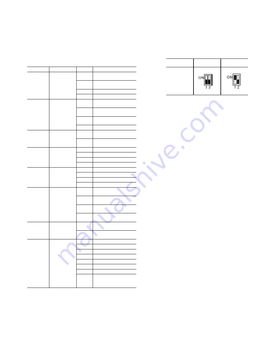
The snow-blowing modes can be selected through S11 dip
switch on spot check box as shown in Fig. 42..

Fig. 42 —S11 - Snow-Blowing Modes

If the unit receives a startup signal, it will exit the snow-
blowing function.

Pre-Start Check

• Check that the refrigerant pipe line and communication

wire with indoor and outdoor unit have been connected
to the same refrigeration system.

• Outdoor units require either 208/230-3-60 or 460-3-60

power. Verify that the power and phase requirements are
correct and all three legs are present. 

• Check that power source’s voltage is within 10% of the

rated voltage.

• Check and confirm that the power and control wire are

correctly connected.

• Check that the wired controllers are properly connected.

• Before powering on, confirm there is no short circuit for

each line.

• Check that all units have passed a nitrogen pressure test

for 24 hours.

• Provide the customer accurate “as-built” drawings and

documents, including actual piping lengths and
locations, unit addresses, settings, etc.

• Ensure additional refrigerant charge calculations are

correct, and that the system is charged accordingly.

• Energize outdoor units for at least 24 hours before

startup to ensure proper oil temperature.

• Ensure all refrigerant valves on outdoor units are fully

open. Ensure oil balancing valves are open for 2 and 3-
module systems. If these valves are not fully open,
equipment damage may occur.

SYMBOL

FUNCTION

ITEM

DESCRIPTION

_n1_

Special 

function for 

debugging

_n12

Forced cooling (62.6

of IDU)

_n13

Forced heating (86

F of 

IDU)

_n14

Cooling test

_n15

Heating Test

_n2_

Refrigerant 

recycle 

function

_n21

Refrigerant recycled to 

outdoor units

_n22

Refrigerant recycled to 

indoor units

_n23

Refrigerant recycled to 

piping

_n26

Maintenance operation

_n3_

Malfunction 

query

_n31

Historical malfunction 

query

_n32

Clear the historical mal-

function

_n4_

Night time 

setting

_n41

6/10H (default)

_n42

6/12H

_n43

8/10H

_n44

8/12H

_n5_

Silent mode 

setting

_n51

Night silent mode

_n52

Silent mode

_n53

Super silent mode

_n54

Silent mode off (default)

_n8_

Static pressure 

mode setting

_n81

Standard static pressure 

mode (default)

_n82

Low static pressure 

mode (reserved)

_n83

Medium static pressure 

mode (reserved)

_n84

High static pressure 

mode (reserved)

_nb_

Temperature 

unit setting

_nb1

Temperature unit 

(Celsius)

_nb2

Temperature unit 

(Fahrenheit)

_nC_

T4 sensor 

(outdoor 

temperature) 

threshold to 

enable 

Auxiliary Heat.  

Aux heat will 

enable when 

outdoor 

temperature 

falls 1.8 F 

below this 

temperature.

_nC1

Auxiliary heat disabled

_nC2

5

°

F

_nC3

15

°

F

_nC4

25

°

F

_nC5

35

°

F

_nC6

45

°

F

_nC7

55

°

F

_nC8

65

°

F

Mode

Heavy Snow 

Mode

Light Snow 

Mode

S11

Summary of Contents for 38VMH Series

Page 1: ... damage The qualified installer or agency must use factory authorized kits or accessories when modifying this product Follow all safety codes Wear safety glasses protective clothing and work gloves Use quenching cloth for brazing operations Have fire extinguisher available Read these instructions thoroughly and follow all warnings or cautions included in literature and attached to the unit Consult...

Page 2: ...ponent System contains oil and refrigerant under pressure To remove a component wear protective gloves and goggles and proceed as follows a Shut off electrical power to unit b Recover refrigerant to relieve all pressure from system using both high pressure and low pressure ports c Traces of vapor should be displaced with nitrogen and the work area should be well ventilated Refrigerant in contact w...

Page 3: ...wrench 1 For removing the side plate screws 90 degree elbow 2 Sizes 072 096 and 120 1 Size 144 For outdoor unit and refrigerant pipe connection Connective pipe accessories 3 1 Sizes 072 096 and 120 only 1 Network Resistor 2 Enhances stability of communication Ring terminal 4 For connecting the power wire ...

Page 4: ...NON DUCTED INDOOR UNITS Nominal kBtu h 80 0 108 0 126 0 160 0 Rated kBtu h 77 0 103 0 120 0 150 0 ELECTRICAL CHARACTERISTICS WITH NON DUCTED INDOOR UNITS Cooling Power Consumption kW 4 10 6 20 8 80 12 10 EER Btu W 14 10 13 20 11 70 10 60 Heating Power Consumption kW 4 50 7 20 9 00 12 10 COP W W 4 29 3 82 3 60 3 40 ELECTRICAL CHARACTERISTICS WITH DUCTED INDOOR UNITS Cooling Power Consumption kW 5 1...

Page 5: ...00 0 ELECTRICAL CHARACTERISTICS WITH NON DUCTED INDOOR UNITS Cooling Power Consumption kW 11 00 12 90 15 30 18 60 23 90 27 00 EER Btu W 12 50 12 30 11 70 10 70 9 70 9 50 Heating Power Consumption kW 12 40 14 70 16 70 18 40 22 80 26 00 COP W W 3 80 3 75 3 62 3 54 3 27 3 20 ELECTRICAL CHARACTERISTICS WITH DUCTED INDOOR UNITS Cooling Power Consumption kW 12 40 14 50 16 60 18 70 24 20 27 40 EER Btu W ...

Page 6: ...CTRICAL CHARACTERISTICS WITH NON DUCTED INDOOR UNITS Cooling Power Consumption kW 11 00 12 90 15 30 18 60 23 90 27 00 EER Btu W 12 50 12 30 11 70 10 70 9 70 9 50 Heating Power Consumption kW 12 40 14 70 16 70 18 40 22 80 26 00 COP W W 3 80 3 75 3 62 3 54 3 27 3 20 ELECTRICAL CHARACTERISTICS WITH DUCTED INDOOR UNITS Cooling Power Consumption kW 12 40 14 50 16 60 18 70 24 20 27 40 EER Btu W 12 00 11...

Page 7: ...N DUCTED INDOOR UNITS Cooling Power Consution kW 24 10 27 00 30 55 34 90 38 60 40 70 EER Btu W 11 10 10 70 10 20 9 80 9 50 9 50 Heating Power Consumption kW 25 90 28 50 31 00 33 70 36 10 38 90 COP W W 3 43 3 31 3 20 3 20 3 20 3 20 ELECTRICAL CHARACTERISTICS WITH DUCTED INDOOR UNITS Cooling Power Consumption kW 25 70 27 40 29 90 35 90 38 30 40 30 EER Btu W 10 60 10 60 10 40 9 50 9 50 9 50 Heating P...

Page 8: ...TED INDOOR UNITS Cooling Power Consumption kW 24 10 27 00 30 50 34 90 38 60 40 70 EER Btu W 11 10 10 70 10 20 9 80 9 50 9 50 Heating Power Consumption kW 25 90 28 50 31 00 33 70 36 10 38 90 COP W W 3 43 3 31 3 20 3 20 3 20 3 20 ELECTRICAL CHARACTERISTICS WITH DUCTED INDOOR UNITS Cooling Power Consumption kW 25 70 27 40 29 90 35 90 38 30 40 30 EER Btu W 10 60 10 60 10 40 9 50 9 50 9 50 Heating Powe...

Page 9: ...ng damage is filed the unit shipping carton and all packing must be retained for physical inspection by the transportation company All units should be stored in the factory shipping carton with internal packaging in place until installation PROTECTING UNITS FROM DAMAGE Do not apply force or pressure to the coil piping or drain stub outs during handling All units should be handled using proper fork...

Page 10: ...s installed in areas that are exposed to ambient temperatures below freezing 32 F should be installed on a snow ice stand as defined by local codes HANDLING THE UNIT The angle of inclination should not be more than 15 when carrying the unit to avoid overturn of the unit Forklift handling When using a forklift for lifting or transporting the unit insert the prongs of the forklift into the rectangul...

Page 11: ...t Fig 9 Outdoor Unit Placement SPACE REQUIRED FOR INSTALLATION AND MAINTENANCE Ensure there is enough space provided for installation and maintenance see Fig 10 below Fig 10 Space Required for Maintenance If the outdoor unit is higher than the surrounding obstacle follow Figs 11 13 Fig 11 Space Required for One Row Fig 12 Space Required for Two Rows Fig 13 Space Required for More Than Two Rows 4 i...

Page 12: ...Fig 15 Removing the Upright Post Screws Rotate the upright posts 5 to 10 degrees lift them up about 2 mm to remove as shown in Fig 16 Fig 16 Removing the Upright Posts Removing the Side Panels Remove the four screws on the top and bottom side panels Lift them up about 3 mm and remove see Fig 17 Fig 17 Removing the Front Panel Step 3 Connect Refrigerant Piping REFRIGERANT PIPING CONNECTIONS Figure ...

Page 13: ...ssible to be installed on both sides of the U shape branch joint The allowable length of the first branch joint which connected to the indoor unit should be equal to or shorter than 131 ft However when the conditions described in Table 7 are met the allowable length can be extended to 295 ft Table 8 shows allowable conditions for increasing refrigerant pipe diameters For a single module it is not ...

Page 14: ... L Equivalent Length 738 La Ld A C E d Actual Length 656 Furthest Equivalent Piping Length From the First Y Joint L1 131 295 C E d Height Difference Height Between Outdoor and Indoor Unit H1 Outdoor Unit Above 164 Outdoor Unit Below 131 Height Between Indoor Units H2 98 CONDITION PIPES TO INCREASE INCREASED PIPE SIZE If distance from the first Y joint to the last Y joint pipes C E d is 131 ft or t...

Page 15: ...e Setup 4 The branch joint must be installed parallel to the ground and the angle of the joint should not be greater than 10 degrees Positioning the branch joint more than 10 degrees from parallel can cause malfunctions See Fig 23 and 23 for correct positioning of the joint Fig 23 Correct Branch Joint Positioning 5 To avoid oil accumulating in the system install the branch joints properly 6 See Fi...

Page 16: ...16 Fig 24 Correct Branch Joint Installation Fig 25 Typical Refrigerant Piping Layout LEGEND 9 See Table 9 10 See Table 10 11 See Table 11 12 See Table 12 13 See Table 13 14 See Table 14 15 See Table 15 ...

Page 17: ...900033 120 144 1 1 8 1 2 40VM900033 1 1 8 5 8 40VM900033 168 240 1 1 8 5 8 40VM900033 1 3 8 3 4 40VM900034 264 312 1 3 8 3 4 40VM900033 1 3 8 7 8 40VM900034 336 432 1 3 8 3 4 40VM900033 1 5 8 7 8 40VM900035 TOTAL CAPACITY CODE OF INDOOR UNIT AT DOWNSTREAM SIDE INDOOR UNIT MAIN PIPE Gas Side in Liquid Side in Below 56 5 8 3 8 56 to 78 3 4 3 8 78 to 112 7 8 3 8 112 to 156 1 1 8 1 2 156 to 224 1 1 8 ...

Page 18: ...h Joint PART NO LOW PRESSURE GAS SIDE JOINT IN LIQUID SIDE JOINTS IN HEAT INSULATION MATERIAL 40VM900021 2 sets 40VM900022 4 sets 40VM900031 2 sets 40VM900032 2 sets 40VM900033 2 sets 40VM900034 2 sets 40VM900035 2 sets ...

Page 19: ...e on the refrigerant bottle move the charging house from the liquid line service port to the suction line service port Open the suction and liquid service valves on the header unit and start the system in cooling mode Slowly open the valve on the refrigerant bottle and carefully release liquid refrigerant into the suction service port If the total calculated charge amount is added completely to th...

Page 20: ...ed in conformance with the code In Canada wiring must comply with CSA C22 1 Electrical Code Figure 30 below shows the location of the outdoor units power terminal block After selecting the power wire strip a suitable length of insulation and attach the ring terminal using the proper crimping tool Use the ring terminals provided to connect the power wiring as shown in Fig 31 Fig 31 Stripping and At...

Page 21: ...t between outdoor and indoor units and within 820 ft between the wired controller and indoor units Communication wires are sold separately but can be obtained through Carrier Figure 34 below shows a typical communication wire from Carrier For typical communication wiring layout see Fig 35 LEGEND 1 Main Power Terminal 2 Ring Terminal 3 Reusable Strain Relief Wire Ties 4 Ribbon 5 Waterproof Connecto...

Page 22: ... 3 P Q HA HB HA HB HA HB HA HB HA HB HA HB P Q Touch screen wired controller HA HB HA HB HA HB HA HB HA HB HA HB NOTE Power from IDU NOTE 24 v AC Power MAXIMUM WIRING LENGTH L1 L3 3937 ft 18AWG 2 Core Stranded Shield L5 3937 ft 18AWG 2 Core Stranded Shield L6 L7 L8 L9 820 ft 18AWG 2 Core Stranded Shield L10 L11 820 ft 18AWG 2 Core Stranded Shield NOTE Network resistor is shipped with the outdoor u...

Page 23: ...the indoor unit side of the communication wires using the connector provided with the accessories as shown in Fig 41 below Fig 41 Connecting the Communication Cable to Indoor Unit to Outdoor Unit using the Supplied Connector START UP Trial Run Set a different address for each indoor unit The addresses can range from 0 to 63 The address can be set randomly using the Automatic Search Address functio...

Page 24: ...search address Default 01 Manual search address 10 Clear indoor units address ENC1 0 Header unit Outdoor unit address dial switch 1 Follower unit 2 Follower unit ENC2 0 3 Reserved ENC4 0 7 Network address setting 0 7 ENC3 S12 0 F Setting the number of indoor units 0 15 000 0 F Setting the number of indoor units 16 31 001 0 F Setting the number of indoor units 32 47 010 0 F Setting the number of in...

Page 25: ...and documents including actual piping lengths and locations unit addresses settings etc Ensure additional refrigerant charge calculations are correct and that the system is charged accordingly Energize outdoor units for at least 24 hours before startup to ensure proper oil temperature Ensure all refrigerant valves on outdoor units are fully open Ensure oil balancing valves are open for 2 and 3 mod...

Page 26: ...ed around the base of the outdoor unit Check for proper condensate drainage clear basepan Eliminate any standing water inside the outdoor unit EVERY 12 MONTHS Follow 6 month maintenance schedule In addition Be sure all electrical connections are secure Check the heating and cooling action to confirm proper operation CAUTION When servicing or repairing this unit use only factory approved service re...

Reviews: