Carier is participating in
the Eurovent Certification
Programme. Products are
as listed in the Eurovent
Directory of Certified
Products.
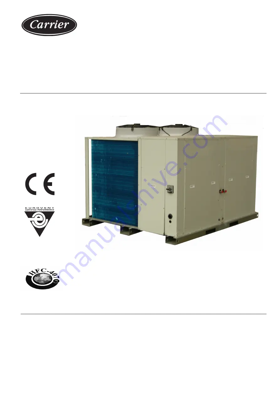
38UQZ 016-020-024
40ALZ 016-020-024
Split-System Air-to-Air
Heat Pumps
Installation, Operation and Maintenance Instructions


