background image

30

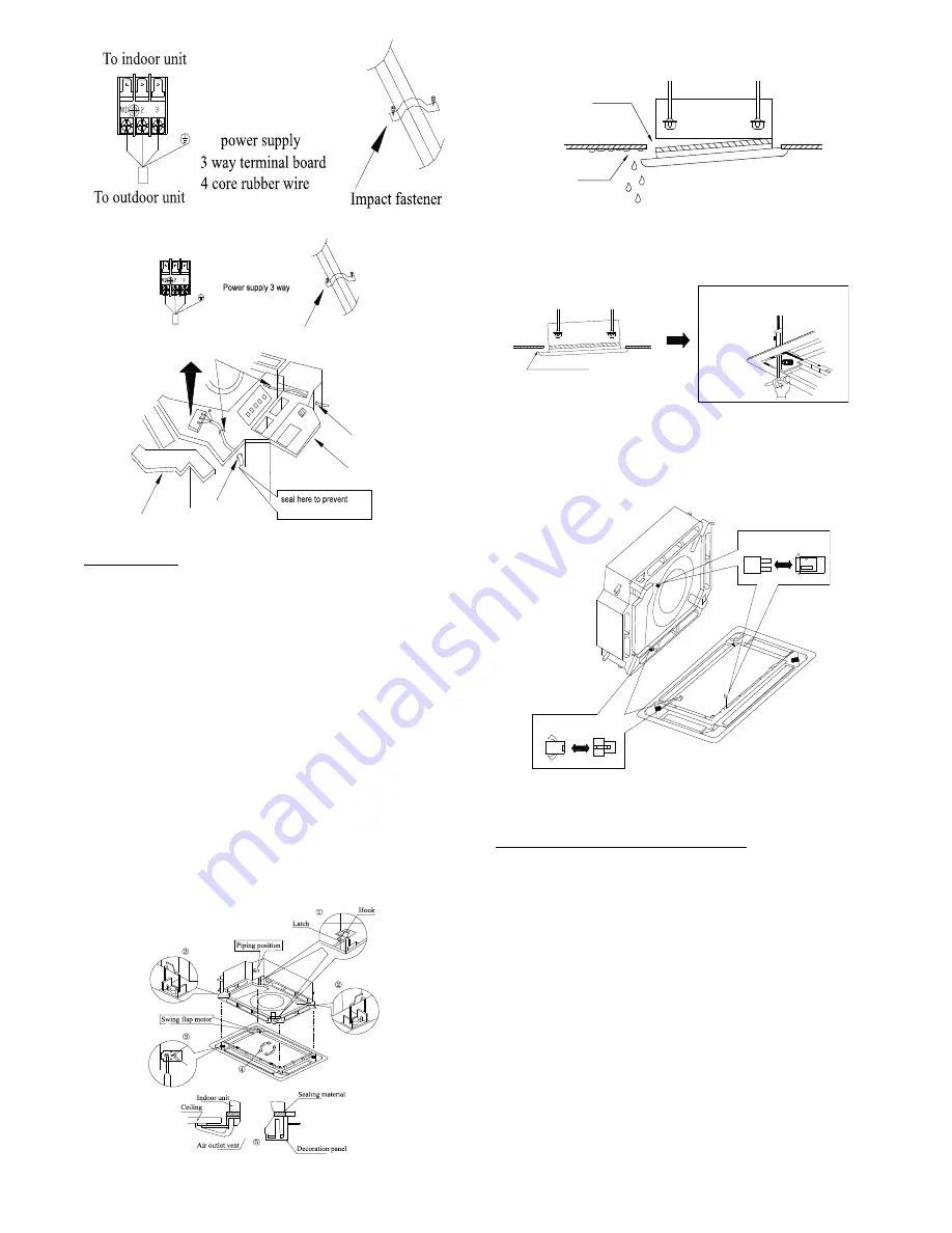
Fig. 40 – Power cord

To indoor unit

To indoor unit

Impact fastener

Electric box cover(1)

Cable-cross loop

Cable-cross loop

water leakage

Electric box cover(2)

terminal board 4 core

rubber wire

Fig. 41 – Power Supply

Install the panel

1 Set the panel to the indoor unit body by matching the position

of the panel’s swing flap motor to the panel’s piping position
to the indoor unit’s piping position (see Fig. 42).

2 Install the panel.

(1.) Install the panel on the indoor unit temporarily. When

installing, hang the latch on the hook located on the
opposite side of the swing flap on the panel of the
indoor unit (two positions).

(2.) Hang the remaining 2 latches to the hooks on the sides

of the indoor unit. Be careful not to let the swing motor
lead wire get caught in the sealing material.

(3.) Screw the 4 hexagon head screws under the latches in

about 3/5 in. (15 mm) and the panel should rise.

(4.) Adjust the panel by turning it toward the direction

pointed by the arrow (see Fig. 42) so the adjust board
connects well to the ceiling.

(5.) Tighten the screws until the thickness of the sealing

material between the panel and the indoor unit is
reduced to 5−8mm.

1/5 in to 1/3 in (5 mm to 8 mm)

Fig. 42 – Panel Installation

NOTE

(1.) Improper screwing of the screws may cause issues (see Fig. 43).

Air leak

Air leak from ceiling

Water condensatation, water drop

Fig. 43 – Example of Improper Screwing Issue

(2.) If a gap still exists between the ceiling and decoration panel

after tightening the screws, re−adjust the height of the indoor
unit (see Fig. 44).

If the raising lever and drain hose are
not affect, can adjust the height of 
indoor unit by the hole on the corner

of panel.

 Gaps are not allowed

Fig. 44 – Improper Screwing

IMPORTANT:


After securing, ensure there is no gap between

the ceiling and the panel.

(3.) Wiring of the decoration panel (Fig. 45). Connect the joints

for the swing flap motor lead wire (at 2 places) onto the panel.

At body

At pane

At body

At pane

Fig. 45 – Connect Joints

Wireless Remote Control Installation

Mounting Bracket (if installed on the wall)

1 Use the two screws supplied with remote controller to attach

the Mounting Bracket to the wall in a location selected by
customer and within operating range.

2 Install batteries in the Remote Controller.

3 Place the Remote Controller in the remote control Mounting

Bracket.

NOTE: For remote control operation, refer to the unit Owner’s
Manual. The wireless remote should pointed to the wired controller
to receive the signal.

Wired Remote Controller (shipped with the unit)

For setup instructions, refer to the wired controller installation
manual. Connect the 4−core wire shipped with the unit to CN9 on
the indoor board and CN1 on the wired controller board.

Summary of Contents for 38GJQ Series

Page 1: ...IREMENTS 6 CONVERSION JOINTS 7 REFRIGERANT PIPING 7 ELECTRICAL DATA 9 WIRING 10 DIMENSIONS INDOOR 11 DIMENSIONS OUTDOOR 17 DIMENSIONS BRANCH BOXES 20 DIMENSIONS PIPING ADAPTERS INCLUDED WITH BRANCH BO...

Page 2: ...ON These words are used with the safety alert symbol DANGER identifies the most serious hazards which will result in severe personal injury or death WARNING signifies hazards which could result in per...

Page 3: ...1 2 1 Table 3 Part List Indoor High Wall 40GJB Size Name Qty 9 12 Mounting Plate 1 Remote Control 1 Remote Control Holder 1 Battery 1 5V 2 Conversion Joint 1 2 to 3 8 1 Table 4 Part List Indoor High W...

Page 4: ...lation Panel 1 Remote Control 1 Remote Control Holder 1 Battery 1 5V 2 Table 8 Part List Branch Box KSAUI0201AAA Name Name Qty Multi 2 Port Branch Box Installation instruction 1 Branch pipe outdoor 3...

Page 5: ...oor unit This ensures that rain drips from the connection pipe before it enters the wall Piping and the interconnecting wiring are field supplied Fig 1 is only a sketch Different models may be differ...

Page 6: ...Table 13 Indoor Piping Connection High Wall Indoor High Wall 40GJB SIZE 9 12 18 24 Pipe Connection Size Liquid in 1 4 1 4 1 4 1 4 Pipe Connection Size Suction in 1 2 1 2 5 8 5 8 Table 14 Indoor Pipin...

Page 7: ...1 2 N A 5 8 N A N A 5 8 N A 9 000 40GJQB09B 3 1 2 1 2 to 3 8 3 8 NA N A 1 2 3 8 to 1 2 N A 1 2 3 8 to 1 2 N A 1 2 3 8 to 1 2 N A 1 2 3 8 to 1 2 1 2 to 5 8 1 2 N A 1 2 to 5 8 1 2 N A 12 000 40GJQB12B...

Page 8: ...A 3 8 to 1 4 1 4 N A 3 8 to 1 4 1 4 N A 18 000 40GJQB18B 3 1 4 N A 1 4 N A N A 1 4 N A N A 1 4 N A N A 1 4 N A 3 8 to 1 4 1 4 N A 3 8 to 1 4 1 4 N A 24 000 40GJQB24B 3 1 4 N A 1 4 N A N A 1 4 N A N A...

Page 9: ...VOLT PHASE HZ MAX MIN FLA HP W 9 208 230 1 60 253 187 0 28 1 24 80 12 0 31 1 18 80 18 0 41 1 12 100 21 0 5 1 36 124 24 0 5 1 36 124 Table 24 Floor Console UNIT SIZE SYSTEM VOLTAGE OPERATING VOLTAGE IN...

Page 10: ...wered by the Branch Boxes The field supplied 14 3 stranded wire with ground with a 600 volt insulation rating power communication wiring from the BRANCH BOXES to INDOOR UNITS consists of four 4 wires...

Page 11: ...ions Table 26 40GRQ High Wall Dimensions UNIT SIZE W In mm D In mm H In mm Q In mm OPERATING WEIGHT Lbs kg 9k 37 8 960 8 07 205 12 6 320 2 16 55 33 07 15 12k 37 8 960 8 07 205 12 6 320 2 16 55 33 07 1...

Page 12: ...R CONT Fig 3 40GJB High Wall Dimensions Table 27 40GJB High Wall UNIT SIZE W In mm D In mm H In mm OPERATING WEIGHT 9k 34 09 8 23 11 5 24 3 12k 34 09 8 23 11 5 24 3 18k 40 079 9 055 12 6 30 9 24k 46 3...

Page 13: ...Size 12 and 18 Cassette Dimensions Table 28 Size 12 and 18 Cassette Dimensions SYSTEM SIZE 12 18 Height H in cm 9 1 23 1 9 1 23 1 Width W in cm 22 4 56 9 22 4 56 9 Depth D in cm 22 4 56 9 22 4 56 9 We...

Page 14: ...MENSIONS INDOOR CONT Fig 5 Size 24 Cassette Dimensions Table 29 Size 24 Cassette Dimensions SYSTEM SIZE 24 Height H In CM 9 4 23 9 Width W In CM 33 1 84 1 Depth D In CM 33 1 84 1 Weight Net Lbs Kgs 61...

Page 15: ...in 782 mm 6 1 7 in 156 mm 7 7 8 in 200 mm 25 in 635 mm 40GJQB12D 3 40GJQB18D 3 37 in 942 mm 19 1 3 in 491 mm 34 in 862 mm 32 2 7 in 820 mm 35 3 7 in 900 mm 24 1 5 in 615 mm 38 2 3 in 982 mm 6 1 7 in...

Page 16: ...16 DIMENSIONS INDOOR CONT 8 4 in 215mm 23 6in 600mm 27 5in 700mm 7 87in 200mm Fig 7 Floor Console Dimensions...

Page 17: ...R Unit in mm 34 8 in 883 92 mm 12 3 in 312 42 mm 27 6 in 701 04 mm Unit in mm Fig 8 Outdoor Dimensions Size 18 Unit in mm 34 8 in 883 92 mm 12 3 in 312 42 mm 30 6 in 777 24 mm Unit in mm Fig 9 Outdoor...

Page 18: ...in 976 09 mm 17 33 in 440 27 mm 15 71 in 399 14 mm 24 in 609 6 mm Unit in mm Fig 10 Outdoor Dimensions Size 30 40 in 1016 mm 42 5 in 1079 5 mm 24 83 in 630 77 mm 17 33 in 440 27 mm 14 25 in 361 95 mm...

Page 19: ...19 DIMENSIONS OUTDOOR CONT Fig 12 Outdoor Dimensions Size 48 56...

Page 20: ...7 in 80 mm 2 2 5 in 61 mm 3 1 2 in 88 mm 7 1 6 in 182 mm 3 1 3 in 85 mm 2 1 2 in 64 mm Fig 13 Outline Dimensions Table 31 Outline Dimensions Sorts Indoor Unit Side inch mm Outdoor Unit Side inch mm Po...

Page 21: ...mm 23 4in 70mm 1 4 5in 35mm 23 4in 70mm 23 4in 70mm Fig 15 Outline Dimensions Table 33 Outline Dimensions Sorts Indoor Unit Side inch mm Outdoor Unit Side inch mm PORT A PORT B PORT C Liquid pipe 1 4...

Page 22: ...ping Adapter Outdoor L 64in 16 1mm m m 8 3 1 n i 3 4 5 51in 12 9mm 38in 9 7mm 6in 4 3in 2 75in 150mm 110mm 70mm L Length 70in 18mm 39in 10mm 79in 20mm 79in 20mm 47in 12mm Fig 18 Piping Adapter Indoor...

Page 23: ...63 in 16 1mm 62 in 15 8mm 59 in 15mm 59 in 15mm 2 13 in 54mm 9 53 in 242mm 20 in 5mm 3 347 in 85 mm 47in 12mm 94 in 24mm 98 in 25mm 94 in 24mm 79 in 20mm 39 in 10mm Unit in mm Fig 20 Branch Pipe Gas P...

Page 24: ...24 CLEARANCES INDOOR 6 0 15m min 5 0 13m min 6 5 0 13m min 1 8m CEILING FLOOR Fig 22 High Wall Clearance Fig 23 Cassette Clearance...

Page 25: ...25 CLEARANCES INDOOR CONT Fig 24 Ducted Clearance Fig 25 Floor Console Clearance...

Page 26: ...E Fig 26 Clearances Outdoor 18 42 Table 35 Clearances Outdoor UNIT MINIMUM VALUE in mm A 24 609 B 24 609 C 24 609 D 4 101 E 4 101 Fig 27 Clearances Outdoor 48 56 NOTE Outdoor unit must be mounted at...

Page 27: ...t a b c As viewed from front Knockout 3 Knockout 2 Knockout 1 A08281 Fig 28 Refrigerant Line Routing If piping is going through the back S Determine the pipe hole position using the mounting plate as...

Page 28: ...2 m m 4 0 6 n i 9 7 3 2 m m 0 5 6 n i 5 3 5 2 Install dimension of mode 37 2 5 in 950 mm 37 2 5 in 950 mm 35 in 890 mm 35 in 890 mm 33 in 840 mm 33 in 840 mm 30 5 7 in 780 mm 267 9 in 680 mm Fig 31 D...

Page 29: ...in Hose NOTE Drain Setup pipe S The install height of the drain raising pipe should less than 11 in 280 mm S The drain raising pipe should form a right angle with the unit and distance to unit should...

Page 30: ...cause issues see Fig 43 Air leak Air leak from ceiling Water condensatation water drop Fig 43 Example of Improper Screwing Issue 2 If a gap still exists between the ceiling and decoration panel after...

Page 31: ...nit on the ceiling as shown in Fig 48 48mm Fig 48 Install the indoor unit S Prior to the installation prepare for all piping refrigerant pipe drain pipe and wiring wires of the wired controller wires...

Page 32: ...D 09 6 1 7 in 156 mm 26 in 662 mm 22 5 6 in 580 mm 22 5 6 in 580 mm 12 18 6 1 7 in 156 mm 34 in 862 mm 30 5 7 in 780 mm 6 3 8 in 162 mm 21 6 1 7 in 156 mm 41 4 5 in 1062 mm 38 4 7 in 980 mm 6 3 8 in...

Page 33: ...ded a lift pipe should be installed 4 Keep a distance of 3 28 ft 4 92 ft 1m 1 5m between the hangers to avoid the drain hose from turning 3 28 ft 4 92 ft 1m 1 5 m Wrong Fig 57 Slope Degree 5 Insert th...

Page 34: ...start type as they may shorten the remote controller range 8 The unit is at least 3 28 ft 1m away from any television or radio set unit may cause interference with the picture or sound NOTE DO NOT in...

Page 35: ...embedded pipe and wall cover in the feed through hole to prevent water leakage S Be sure to caulk the gaps around the pipes with caulking material to prevent water leakage 1 Bore a feed through hole...

Page 36: ...Side casings 2 Upper casing 3 Side casings Remove the pillar Remove 7 screws Fig 71 Remove the screws For Side Piping Remove the pillars 1 Remove the 7 screws 2 Remove the upper casing 2 tabs 3 Remove...

Page 37: ...as this would reduce the lifetime of the units 3 Never use piping which had been used for previous installations Only use parts which are delivered with the unit 4 Do never install a drier to this R41...

Page 38: ...or unit They are required for certain fan coil combinations These joints are to be connected to the outdoor unit as needed to match the line set size 4 Cut tubing with a tubing cutter 5 Install the co...

Page 39: ...es and nine different types of indoor units high wall cassette ducted and floor console At least one Branch Box KSAUI0201AAA up to 2 indoor units or KSAUI0401AAA up to 3 indoor units is required on th...

Page 40: ...ction Display Stop 1 The section displays the numbers of the indoor units which have established communication with the outdoor unit For example if there are sever established indoor units the section...

Page 41: ...Outdoor unit L2 S L1 G L1 L2G POWER BU2 L2 S L1 Indoor unit 2A Indoor unit 2B G Indoor unit 2C G L2 S L1 Indoor unit C Indoor unit B Indoor unit A L2 L1 POWER L2 S G BU2 Outdoor unit BU module L2 S B...

Page 42: ...42 Connection Diagrams 18 42 Fig 82 Connection Diagram Sizes 18 42 48 56 Fig 83 Connection Diagram Sizes 48 56 Connection Diagram Fig 84 Connection Diagram Branch Box...

Page 43: ...in the wall 11 Repeat steps 1 through 10 for each indoor unit System Vacuum and Charge UNIT DAMAGE HAZARD Failure to follow this caution may result in equipment damage or improper operation Never use...

Page 44: ...heck to ensure the factory tubing on both the indoor and outdoor unit has not shifted during shipment Ensure the tubes are not rubbing against each other or any sheet metal Pay close attention to the...

Page 45: ...h remote controller within 200s displayed directly on nixie tube after 200s P8 Refrigerant lacking or blockage protection of system not available for residential ODU F0 Charging malfunction of capacit...

Page 46: ...oor ambient sensor malfunction Flash 6 times F3 Outdoor tube sensor malfunction Flash 5 times F4 Exhaust sensor malfunction Flash 7 times F5 Attain the temperature of switch on Flash 8 times Frequency...

Page 47: ...nt protection Flash 21 times L9 L9 Compressor overload protection Flash 22 times H3 H3 Compressor discharge temperature protection Flash 23 times E4 E4 Lack of refrigerant or jam protection Flash 31 t...

Page 48: ...main board and testing board CE Indoor unit gas sensor error Fn Indoor unit humidity sensor error L1 Indoor unit water full protection E9 Jumper terminal error C5 C5 Power supply phase lack dJ Outdoo...

Reviews: