


25
Liquid Line Filter Drier —
The factory-provided filter
drier is specifically designed to operate with Puron
®
.
Replace the filter drier with factory-authorized components
only with a filter drier with desiccant made from 100%
molecular sieve grade XH-11. Filter drier must be replaced
whenever the refrigerant system is opened.
When removing a filter drier, use a tubing cutter to cut the
drier from the system.
Do not unsweat a filter drier
from
the system. Heat from unsweating will release moisture
and contaminants from drier into system.
Field Refrigerant Access Ports —
Field service access to
refrigerant pressures is through the access ports located at
the service valves (see Figs 26 and 28). These ports are
1
/
4
-in SAE Flare couplings with Schrader check valves
and service caps. Use these ports to admit nitrogen to the
field tubing during brazing, to evacuate the tubing and
evaporator coil, to admit initial refrigerant charge into the
low-side of the system and when checking and adjusting
the system refrigerant charge. When service activities are
completed, ensure the service caps are in place and
secure; check for leaks. If the Schrader check valve must
be removed and re-installed, tighten to 23-34 N-cm (2-3
in-lbs).
Factory High-Flow Access Ports —
There are two
additional access ports in the system - on the suction tube
between the compressor and the suction service valve and
on the liquid tube near the liquid service valve (see Fig.
23 and Fig. 25). These are brass fittings with black plastic
caps. The hose connection fittings are standard
1
/
4
-in SAE
Male Flare couplings.
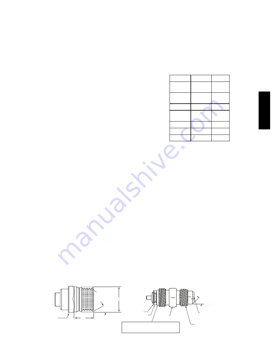
The brass fittings are two-piece High Flow valves, with a
receptacle base brazed to the tubing and an integral
spring-closed check valve core screwed into the base. (See
Fig. 20.) This check valve is permanently assembled into
this core body and cannot be serviced separately; replace
the entire core body if necessary. Service tools are
available from RCD that allow the replacement of the
check valve core without having to recover the entire
system refrigerant charge. Apply compressor refrigerant
oil to the check valve core’s bottom o-ring. Install the
fitting body with 1085
±
23 N-cm (96
±
-10 in-lbs) of
torque; do not overtighten.
Comfort Alert Diagnostic Module
The Comfort Alert Diagnostic Module (CADM) monitors
and analyzes data from the Copeland Scroll
®
three-phase
compressor and the thermostat demand. The CADM also
provides a 3-minute anti-recycle time delay to compressor
cycling.
The CADM detects causes for electrical and system
related failures without any sensors. Flashing LEDs
communicate the Alert codes to guide service technicians
in accurately and quickly troubleshooting the system and
determining root cause for the failure.
Inputs to the CADM include 24-vac power, thermostat
Y1, compressor contactor coil (common side) and
compressor power leads (from the compressor contactor).
Input
Terminal
Voltage
Control
Power
R
24-V
Control
Common
C
24-V
Cooling
Y
24-V
Contactor
Coil
P
24-V
Line A
T1
Line
Line B
T2
Line
Line C
T3
Line
Control of the compressor contactor coil is through a
normally-closed (power on the module) contact between
terminals P and C.
Communications of status and alert conditions is through
three LEDs located on the top edge of the module housing
(see Fig. 21): POWER (green), ALERT (yellow), and
TRIP (red).
The POWER LED indicates the presence of control power
to the CADM.
The ALERT LED indicates an abnormal condition exists
in the system through a flash code. The ALERT LED will
blink a number of times consecutively, pause and the
repeat the process. The number of blinks, defined in Table
9, correlates to a particular abnormal condition;
troubleshooting tips are provided for each Alert code.
Reset of the ALERT may be automatic or manual. If the
fault condition causing the Alert is self-corrected, the
Alert code will be removed and the CADM will
automatically reset and allow the system to restart
normally. Manual reset requires that main power to the
38AUD unit be recycled after the cause for the Alert
condition has been detected and corrected.
1/2-20 UNF RH
30°
0.596
.47
5/8” HEX
SEAT
CORE
WASHER
DEPRESSOR PER ARI 720
+.01/-.035
FROM FACE OF BODY
7/16-20 UNF RH
O-RING
45°
1/2" HEX
This surface provides a metal to metal seal when
torqued into the seat. Appropriate handling is
required to not scratch or dent the surface.
(Part No. EC39EZ067)
C08453
Fig. 20 -- CoreMax Access Port Assembly
38A
U
D
Summary of Contents for 38AUD*12 Series
Page 21: ...21 Fig 19 38AUZ 07 Charging Chart Fig 20 38AUZ 08 Charging Chart...
Page 22: ...22 Fig 21 38AUD 12 Charging Chart...
Page 23: ...23 Fig 22 38AUD 14 Charging Chart...
Page 24: ...24 Fig 23 Typical 38AUZ Wiring Diagram 50Hz Single Circuit Unit Shown...
Page 25: ...25 Fig 24 Typical 38AUD Wiring Diagram 50Hz Dual Circuit Unit Shown...
Page 61: ...21 C10084 Fig 18 Typical 38AUD 16 Wiring Diagram 38AUD...
Page 62: ...22 C10085 Fig 19 Typical 38AUD 25 Wiring Diagram 38AUD...