background image

I N S T A L L A T I O N ,   O P E R A T I O N   A N D 
M A I N T E N A N C E   I N S T R U C T I O N S

Water-Cooled/Condenserless

Liquid Chillers/Water-Sourced Heat Pumps 

with or without Integrated Hydronic Module

61WG/30WG/30GA 020-090

Original document

Nominal cooling capacity 25-95 kW

Nominal heating capacity 29-117 kW

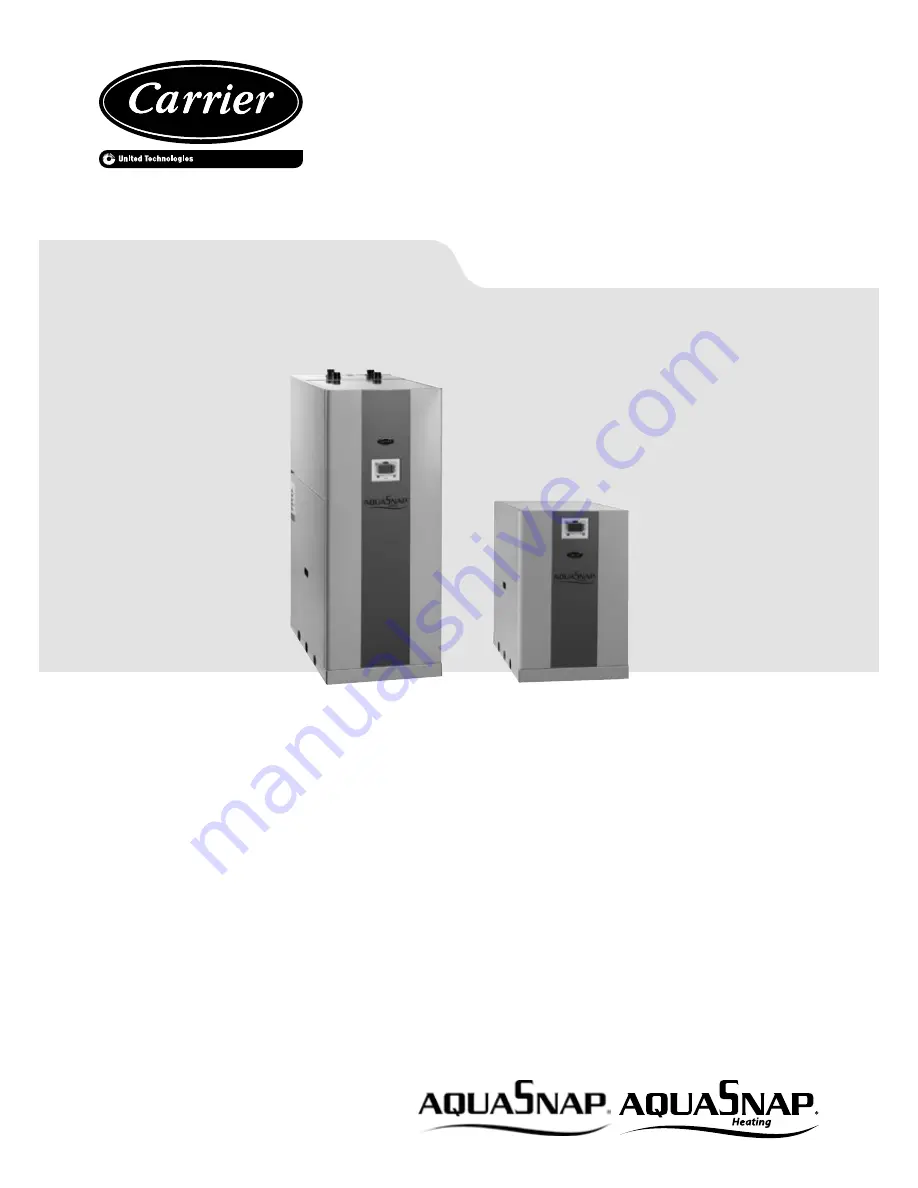
Unit with optional hydronic module

Standard unit

PRO-DIALOG

Summary of Contents for 30WG 020

Page 1: ...O N S Water Cooled Condenserless Liquid Chillers Water Sourced Heat Pumps with or without Integrated Hydronic Module 61WG 30WG 30GA 020 090 Original document Nominal cooling capacity 25 95 kW Nominal heating capacity 29 117 kW Unit with optional hydronic module Standard unit PRO DIALOG ...

Page 2: ...050 090 unit with hydronic module and top connections options 116 274 or 270 274 116 or 270 274 16 3 14 61WG 30WG 050 090 stackable unit option 273 16 3 15 30WGA 020 045 standard unit 17 3 16 30WGA 020 045 unit with evaporator hydronic module option 116 17 3 17 30WGA 020 045 stackable unit option 273 18 3 18 30WGA 050 090 standard unit 18 3 19 30WGA 050 090 unit with evaporator hydronic module opt...

Page 3: ...F 61WG UNITS WITH SPECIFIC HEATING CONTROL OPTION 153 39 12 1 Operating principle 39 12 2 Auxiliary electronic board AUX1 analogue and digital inputs and outputs 39 13 OPERATION OF 61WG UNITS WITH THE HEATING SYSTEM MANAGER HSM 40 14 30WG UNIT OPERATION WITH A DRYCOOLER OPTION 154 41 14 1 Operating principle 41 14 2 Auxiliary electronic board AUX1 analogue and digital inputs and outputs to control...

Page 4: ...7 14 Option 272 High temperature water production with glycol solution 47 17 15 Outside air temperature sensor 47 18 OPTIONS AND ACCESSORIES 48 19 MAINTENANCE 49 19 1 Soldering and welding 49 19 2 General system maintenance 49 19 3 Refrigerant undercharge 49 19 4 Refrigerant guidelines 49 19 5 Leak detection 50 19 6 Evacuation 50 19 7 Recharging liquid refrigerant 50 19 8 Characteristics of R 410A...

Page 5: ...the case there is a risk of material deterioration and injuries to personnel DO NOT COVER ANY PROTECTION DEVICES 30WGAaresuppliedwithoutsafetyvalveonthehigh pressure refrigerant circuit and are equipped with automa tically reset pressure switches in accordance with EN378 For unit installation and connection to the remote condenser it is necessary to Check the applicable air conditioning regulation...

Page 6: ...nits are intended to be stored and operated in an environment where the ambient temperature must be not less than the lowest allowable temperature indicated on the nameplate Do not introduce significant static or dynamic pressure with regard to the operating pressures used during operation or for tests in the refrigerant circuit or in the heat exchange circuits 1 3 Maintenance safety consideration...

Page 7: ...r the unit The company or organisation that conducts a pressure switch test shall establish and implement a detailed procedure to fix Safety measures Measuring equipment calibration Validating operation of protective devices Test protocols Recommissioning of the equipment Consult Carrier Service for this type of test Carrier mentions here only the principle of a test without removing the pressure ...

Page 8: ...cribed in standard NF E29 795 Any refrigerant transfer and recovery operations must be carried out using a transfer unit 3 8 SAE connectors on the liquid suction and discharge lines are available for all units for connection to the transfer station The units must never be modified to add refrigerant and oil charging removal and purging devices All these devices are provided with the units Please r...

Page 9: ...l crushing Use struts or lifting beams to spread the slings above the unit Do not tilt a unit more than 15 or 5 for units with the stacking option option 273 Always follow the instructions on the handling notice attached to the unit If a unit includes a hydronic module options 116 or 270 the hydronic module and pump piping must be installed in 1 5 Measures provisions procedures against emergencies...

Page 10: ...r dimensional drawings P ID declarations etc to comply with the regulations are present Verify that the environmental safety and protection and devices and arrangements provided by the manufacturer to comply with the regulations are in place Verifythatalldocumentsforpressurecontainers certificates name plates files instruction manuals provided by the manufacturertocomplywiththeregulationsarepresen...

Page 11: ...t Water outlet Power wiring connection 161 237 153 470 160 237 153 470 1058 900 700 700 1044 600 625 901 700 2 2 1 1 4 4 4 4 5 3 3 3 2 61WG 30WG 020 045 unit with top connections option 274 901 938 86 105 104 105 143 1044 600 700 900 700 700 700 2 1 4 4 4 4 4 Only for option 70F NOTE Non contractualdrawings Refertothecertifieddimensionaldrawingsavailable on request when designing an installation ...

Page 12: ...470 868 1044 1058 1463 704 600 625 700 379 3 5 1 2 2 1 4 3 4 4 4 153 398 153 161 623 1021 142 237 2 2 1 1 398 153 470 398 161 142 623 2 2 1 1 Legend All dimensions are in mm Evaporator Condenser Safety valve Clearances required for maintenance see note Control box Water inlet Water outlet Power wiring connection Only for option 70F NOTE Non contractual drawings Refer to the certified dimensionaldr...

Page 13: ...tion 273 NOTE The water and electrical connections are identical to those of the standard unit 1014 1014 1058 600 1841 900 700 700 700 4 4 4 4 Legend All dimensions are in mm Evaporator Condenser Safety valve Clearances required for maintenance see note Control box Water inlet Water outlet Power wiring connection NOTE Non contractualdrawings Refertothecertifieddimensionaldrawingsavailable on reque...

Page 14: ...3 3 700 900 700 253 142 168 142 80 1474 901 938 880 700 700 2 1 4 4 4 4 4 Legend All dimensions are in mm Evaporator Condenser Safety valve Clearances required for maintenance see note Control box Water inlet Water outlet Power wiring connection Only for option 70F NOTE Non contractualdrawings Refertothecertifieddimensionaldrawingsavailable on request when designing an installation 4 4 4 4 ...

Page 15: ...0 090 unit with condenser hydronic module option 270 3 12 61WG 30WG 050 090 unit with evaporator condenser hydronic modules options 116 270 Legend All dimensions are in mm Evaporator Condenser Safety valve Clearances required for maintenance see note Control box Water inlet Water outlet Power wiring connection Only for option 70F NOTE Non contractual drawings Refer to the certified dimensional dra...

Page 16: ...70 274 3 14 61WG 30WG 050 090 stackable unit option 273 NOTE The water and electrical connections are identical to those of the standard unit Legend All dimensions are in mm Evaporator Condenser Safety valve Clearances required for maintenance see note Control box Water inlet Water outlet Power wiring connection NOTE Non contractualdrawings Refertothecertifieddimensionaldrawingsavailable on reques...

Page 17: ... standard unit 3 16 30WGA 020 045 unit with evaporator hydronic module option 116 Legend All dimensions are in mm Evaporator Condenser Safety valve Clearances required for maintenance see note Control box 6 Refrigerant inlet 7 Refrigerant outlet Water inlet Water outlet Power wiring connection NOTE Non contractual drawings Refer to the certified dimensional drawings available on request when desig...

Page 18: ...learances required for maintenance see note Control box 6 Refrigerant inlet 7 Refrigerant outlet Water inlet Water outlet Power wiring connection NOTE Non contractual drawings Refer to the certified dimensional drawings available on request when designing an installation 3 17 30WGA 020 045 stackable unit option 273 NOTE The water and electrical connections are identical to those of the standard un...

Page 19: ...e see note Control box 6 Refrigerant inlet 7 Refrigerant outlet Water inlet Water outlet Power wiring connection NOTE Non contractual drawings Refer to the certified dimensional drawings available on request when designing an installation 3 19 30WGA 050 090 unit with evaporator hydronic module option 116 3 20 30WGA 050 090 stackable unit option 273 NOTE The water and electrical connections are ide...

Page 20: ... free field The sound levels only apply to units without options Declared dualnumber noise emission values in accordance with ISO 4871 with an associated uncertainty of 3dB A 4 2 Physical data 30WG 30WG 020 025 030 035 040 045 050 060 070 080 090 Operating weight kg 191 200 200 207 212 220 386 392 403 413 441 Sound levels Sound power level 10 12 W dB A 67 0 68 5 69 0 69 3 70 0 70 1 71 5 72 0 72 0 ...

Page 21: ...ce with ISO 9614 1 measured in a free field The sound levels only apply to units without options Declared dualnumber noise emission values in accordance with ISO 4871 with an associated uncertainty of 3dB A 4 4 Physical data 61WG 30WG 30WGA units with hydronic module 61WG 30WG 30WGA 020 025 030 035 040 045 050 060 070 080 090 Operating weight 30WG 61WG option 116V 270V kg 305 313 313 321 327 334 5...

Page 22: ...rating current of the smallest compressor s locked rotor current or limited start up current of the largest compressor Maximum power input at the unit operating limits Values obtained at standardised Eurovent conditions evaporator entering leaving water temperature 12 C 7 C condenser entering leaving water temperature 30 C 35 C Maximum unit operating current at maximum unit power input and 400 V M...

Page 23: ... 25 30 35 40 45 50 60 70 80 90 1 Nominal efficiency at full load and nominal voltage 83 4 83 4 83 4 83 4 83 4 83 4 84 8 84 8 84 8 84 8 84 8 1 Nominal efficiency at 75 rated load and nominal voltage 81 2 81 2 81 2 81 2 81 2 81 2 82 2 82 2 82 2 82 2 82 2 1 Nominal efficiency at 50 rated load and nominal voltage 78 3 78 3 78 3 78 3 78 3 78 3 79 79 79 79 79 2 Efficiency level IE3 3 Year of manufacture...

Page 24: ...ndations of IEC 60364 are accepted as compliance with the requirements of the installation directives Conformance with EN 60204 1 is the best means of ensuring compliance with the Machines Directive 1 5 1 Annex B of EN 60204 1 describes the electrical characteristics used for the operation of the machines 1 The operating conditions for the units are specified below Environment Environment as class...

Page 25: ...ost protection solution must be used For applications with a condenser entering temperature below 15 C the use of a three way valve is recommended This three way valve can be controlled by the 0 10 V analogue output of the Pro Dialog control For a water flow rate that corresponds to a maximum water side temperature difference of 5 K 5 2 Operating range 61WG Condenser leaving water temperature C Ev...

Page 26: ...dium temperature application 5 5 Operating limits 30WGA 5 10 Water flow rates 5 10 1 Standard 61WG 61WG Evaporator water flow rate l s Minimum Minimum Maximum Maximum Low pressure High pressure Low pressure High pressure 020 1 0 0 9 0 5 3 1 3 6 3 8 025 1 0 1 0 0 5 3 3 3 8 4 1 030 1 0 1 0 0 5 3 3 3 8 4 1 035 1 1 1 1 0 6 3 6 4 2 4 7 040 1 2 1 1 0 6 3 8 4 4 5 0 045 1 2 1 1 0 8 4 0 4 6 5 4 050 1 6 1 4...

Page 27: ...w pressure High pressure 020 1 4 1 3 0 5 025 1 5 1 3 0 5 030 1 5 1 3 0 5 035 1 6 1 5 0 6 040 1 7 1 5 0 6 045 1 8 1 5 0 8 050 2 5 2 2 0 8 060 2 2 2 3 1 0 070 2 2 2 4 1 1 080 2 3 2 4 1 3 090 2 5 2 5 1 5 Option 6 Glycol solution production very low temperature Units with hydronic module Minimum flow rate for a maximum permitted temperature difference at the minimum leaving water temperature Units wit...

Page 28: ... unit without hydronic module Water only 61WG 30WG 020 045 1 61WG 30WG 020 2 61WG 30WG 025 to 61WG 30WG 030 3 61WG 30WG 035 4 61WG 30WG 040 5 61WG 30WG 045 6 61WG 30WG 050 7 61WG 30WG 060 8 61WG 30WG 070 9 61WG 30WG 080 10 61WG 30WG 090 61WG 30WG 050 090 Pressure drop kPa Water flow rate l s Pressure drop kPa Water flow rate l s Pressure drop kPa Water flow rate l s Pressure drop kPa Water flow ra...

Page 29: ... the unit with an incorrect supply voltageorexcessivephaseimbalanceconstitutesabusewhich will invalidate the Carrier warranty If the phase imbalance exceeds 2 for voltage or 10 for current contact your local electricity supply at once and ensure that the unit is not switched on until corrective measures have been taken 6 3 Voltage phase imbalance 100 x max deviation from average voltage Average vo...

Page 30: ...ting No 41 PVC insulated cable if possible Section Section Max length for voltage drop 5 Cable type Section Max length for voltage drop 5 Cable typee mm per phase mm per phase m mm par phase m 020 1 x 35 1 x 2 5 60 PVC Cu 1 x 4 100 PVC Cu 025 1 x 35 1 x 2 5 60 PVC Cu 1 x 4 100 PVC Cu 030 1 x 35 1 x 4 80 PVC Cu 1 x 6 120 PVC Cu 035 1 x 35 1 x 4 80 PVC Cu 1 x 6 120 PVC Cu 040 1 x 35 1 x 4 80 PVC Cu ...

Page 31: ...rd AUX 1 To assign the fan stages refer to chapters 14 and 15 with the description of the analogue and digital inputs and outputs Make the communication bus connection twisted and shielded cable type for communication bus RS485 between the specific electronicAUX 1 board that must be integrated in the condenser control box and using the NRCP master board of the 30WG unit The Pro Dialog control is u...

Page 32: ...t is not pressure tight to avoid significant pressurerisesoftheliquidrefrigerantthatmaybetrapped between the solenoid valve tight and the check valve 8 2 Pipe sizing The following procedure can be used for pipe sizing 1 Measure the length in metres of the piping under consideration 2 Add 50 to take account of special characteristics 3 Read the pipe size from tables 1 and 2 below 4 Calculate the eq...

Page 33: ...1 25 1 25 1 The admissible pressure drops in the liquid lines depend mainly on the subcooling level of the liquid refrigerant at the condenser outlet Pressure drops corresponding to 1 5 C saturated temperature must not be exceeded If the liquid refrigerant head is very high it may be necessary to increase the subcooling to prevent a phase change in the liquid line A liquid vapour heat exchanger or...

Page 34: ...lter i e without option 293 or 293A is not covered by the warranty Before the system start up verify that the water circuits are connected to the appropriate heat exchangers e g no reversal between evaporator and condenser Do not introduce any significant static or dynamic pressure into the heat exchange circuit with regard to the design operating pressures Before any start up verify that the heat...

Page 35: ...interlock auxiliary contact for pump operation to be wired on site 10 NOMINAL WATER FLOW CONTROL WITH FIXED SPEED PUMP 10 1 General The water circulation pumps of the 61WG 30WG units have been sized to allow the hydronic modules to cover all possible configurations based on the specific installation conditions i e for various temperature differences between the entering and the leaving water T at ...

Page 36: ...ow rate l s Legend 1 Unit pump curve 2 Plate heat exchanger pressure drop to be measured with the pressure gauge installed at the water inlet and outlet 3 Installation pressure drop with control valve wide open 4 Installation pressure drop after valve control to obtain the specified flow rate Pressure drop kPa 1 2 3 4 0 25 50 75 100 125 150 175 200 2 4 6 8 10 11 NOMINAL WATER FLOW CONTROL WITH VAR...

Page 37: ...61WG 30WG 30WGA 090 1 61WG 30WG 020 2 61WG 30WG 025 to 030 3 61WG 30WG 035 4 61WG 30WG 040 5 61WG 30WG 045 6 61WG 30WG 050 7 61WG 30WG 060 8 61WG 30WG 070 9 61WG 30WG 080 10 61WG 30WG 090 61WG 30WG 30WGA 020 045 61WG 30WG 30WGA 050 090 61WG 30WG 020 045 61WG 30WG 050 090 Pressure head kPa Water flow rate l s Pressure head kPa Water flow rate l s Pressure head kPa Water flow rate l s Pressure head ...

Page 38: ...30WGA 050 090 Pressure head kPa Water flow rate l s Pressure head kPa Water flow rate l s Pressure head kPa Water flow rate l s Water flow rate l s Pressure head kPa Condenser 61WG 30WG 020 045 61WG 30WG 050 090 Data applicable for Fresh water 20 C In case of use of the glycol the maximum water flow is reduced The curves represented below are in normal conditions leaving water on the back side of ...

Page 39: ...e heating loop hot water setpoint reset heating application based on the air temperature priority control between heating application and domestic hot water application NOTE The installer is responsible for ensuring that the installation complies with the applicable legislation in terms of electrical and thermal safety 12 2 Auxiliary electronic board AUX1 analogue and digital inputs and outputs R ...

Page 40: ...perature control and distribution The control box can supply all auxiliary devices such as the circulating pumps or the mixing or switching valves The heat pump is controlled by a CCN bus and the control box includes an NRCP2 BASE board a Pro Dialog interface as well as all required sensors HSM control box dimensions 170 10 382 442 17 17 416 20 5 559 1 5 33 25 536 180 120 52 603 1 1 400 Legend All...

Page 41: ... 12 fans arranged in pairs along the length of the unit will also result in a configuration of 4 or 6 fan stages Configuration with 4 and 6 stages min 2 max 8 14 30WG UNIT OPERATION WITH A DRYCOOLER OPTION 154 14 1 Operating principle 30WG units have been specially designed to optimise the operation of systems using drycoolers as heat rejection system With a variable speed condenser water pump int...

Page 42: ...irst fan to start in each circuit and the last fan to stop A fan configuration with fixed speed fans permits year round system operation down to 0 C outside temperature A fan configuration with a variable speed lead fan permits year round operation down to 10 C outside temperature 15 3 Auxiliary electronic board AUX1 analogue and digital inputs and outputs to control the remote air cooled condense...

Page 43: ...tially closed Pro Dialog controls the automatic switching of all fan stages based on operating time and number of start ups of the different stages This function prevents fan motors from only running a little or not at all and the shafts seizing up especially during periods with a low cooling demand when the outside temperature is low Switching is often specified by the condenser manufacturers to ...

Page 44: ...ith hydronic module Additional sensors for leaving water control to be connected to channel 1 of the slave boards of each master and slave unit CCN communication bus Connection of two additional sensors 17 MAJOR SYSTEM COMPONENTS AND OPERATION DATA 17 1 Compressors 61WG 30WG 30WGA units use hermetic scroll compressors The only refrigerant permitted for these compressors is R 410A 30WGA split units...

Page 45: ...pressor shell may invalidate the right to use the equipment Units using these compressors are installed in areas where the temperature must be between 5 C minimum and 40 C maximum The temperature around the compressors must not exceed 50 C during unit shutdown cycles Shock absorbers are installed under the compressor feet 17 2 Lubricant The compressors have the following factory lubricant charge p...

Page 46: ... high and low pressure side safety valves 30WGA units are only equipped with a low pressure side safety valve The installer must determine which accessories safety valves fuses etc are required to ensure that the completed high pressure circuit complies with the applicable regulations and standards 17 8 Moisture indicator Located in the liquid line permits control of the unit charge as well as the...

Page 47: ...ps are protected by a suction filter This is easily removable to recover solid particles It protects the pump and the plate heat exchanger against solid particles with a size exceeding 1 2 mm Before the unit start up it is important to turn the evaporator and condenser pump to decontaminate the water loops of any solid pollution A specific pump start up function in the Quick Test menu is available...

Page 48: ... Condenser screw connection sleeves 265 Condenser inlet outlet screw connection sleeves Allows unit connection to a screw connector 30WG 020 090 61WG 020 090 Welded evaporator connection sleeves 266 Welded evaporator inlet outlet connection sleeves Allows welding of customer connections to the unit 30WG 020 090 61WG 020 090 30WGA 020 090 Welded condenser connection sleeves 267 Welded condenser inl...

Page 49: ... transfer must be made using mobile containers 19 2 General system maintenance Keep the unit itself and the space around it clean and free of obstructions Remove all rubbish such as packing materials as soon as the installation is completed Regularly clean the exposed pipework to remove all dust and dirt This makes detection of water leaks easier and they can be repaired before more serious faults...

Page 50: ...ocedure steps 1 2 etc 5 Repeat the evacuation procedure steps 1 2 a vacuum level of 0 67 mbar 500 µm Hg must be achieved and maintained for four hours This vacuum level must be measured at one of the system connectionsandnotatthevacuumpumppressuregauge ATTENTION Do not use a megohmmeter and do not place any stress on the compressor motor when the system has been evacuated There is a risk of intern...

Page 51: ...fic compressor problems The following periodic preventive maintenance checks are strongly recommended Checktheoperatingconditions evaporatingtemperature condensing temperature discharge temperature heat exchangertemperaturedifference superheat subcooling These operating parameters must always be within the compressor operating range Check that the safety devices are all operational and correctly c...

Page 52: ...ing of the electric connections contactors disconnect switch and transformer Check the phase direction upstream of the unit and in the customer s electrical data table Check the status of the contactors and fuses Carryoutaquicktest refertothe61WG 30WG 30WGA Pro Dialog Controls manual Mechanical checks Verify the correct operation of the evaporator and condenser pumps with the Quick Test function V...

Page 53: ... connected Electrical circuit protection has been sized and installed properly All terminals are tight All cables and thermistors have been inspected for crossed wires All plug assemblies are tight Check air handling systems All air handlers are operating All chilled water valves are open All fluid piping is connected properly All air has been vented from the system Chilled water pump CWP is opera...

Page 54: ...r is supplied to the unit check the display for any alarms such as phase reversal Follow the TEST function instructions in the Controls and Troubleshooting literature follow the procedure in the Controls IOM Be sure that all service valves are open before beginning the compressor test section To start the unit WARNING Be sure that all service valves are open and all pumps are on before attempting ...

Page 55: ...55 ...

Page 56: ... No 16122 12 2016 Supersedes order No 16122 10 2014 Manufacturer Carrier SCS Montluel France Manufacturer reserves the right to change any product specifications without notice Printed in the European Union ...

Reviews: