


3–13
T-372
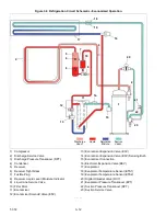
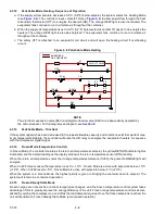
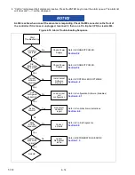
Figure 3.9 Refrigeration Circuit Schematic - Water-Cooled Condenser (Brazed Plate)
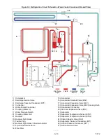
1) Compressor
2) Discharge Service Valve
3) Discharge Pressure Transducer (DPT)
4) Condenser
5) Water-Cooled Condenser
6) Coupling (Water In)
7) Water Pressure Switch
8) Coupling (Water Out)
9) Receiver
10) Receiver Sight Glass
11) Fusible Plug
12) Receiver Sight Glass / Moisture Indicator
13) Liquid Line Service Valve
14) Filter Drier
15) Economizer
16) Economizer Solenoid Valve (ESV)
17) Economizer Expansion Valve (EXV)
18) Economizer Expansion Valve (EXV) Sensing Bulb
19) Economizer Connection
20) Electronic Expansion Valve (EEV)
21) Evaporator
22) Evaporator Temperature Sensor (ETS1)
23) Evaporator Temperature Sensor (ETS2)
24) Digital Unloader Valve (DUV)
25) Evaporator Pressure Transducer (EPT)
26) Suction Pressure Transducer (SPT)
27) Suction Service Valve
- - - - -
Discharge
Vapor
Liquid
Saturated
Mixture
Suction
Vapor