

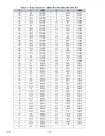


T-372
7–44
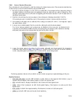
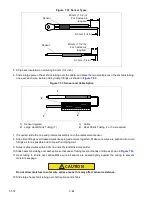
Figure 7.32 Sensor Types
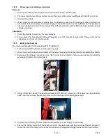
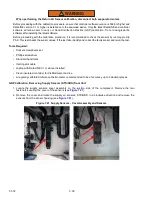
5. Strip back insulation on all wiring 6.3 mm (1/4 inch).
6. Slide a large piece of heat shrink tubing over the cable, and place the two small pieces of heat shrink tubing,
one over each wire, before adding crimp fittings as shown in
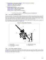
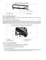
Figure 7.33 Sensor and Cable Splice
1) Sensor (typical)
2) Large Heat Shrink Tubing (1)
3) Cable
4) Heat Shrink Tubing, 2 or 3 as required
- - - - -
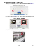
7. If required, slide the cap and grommet assembly onto the replacement sensor.
8. Slip crimp fittings over dressed wires (keeping wire colors together). Make sure wires are pushed into crimp
fittings as far as possible and crimp with crimping tool.
9. Solder spliced wires with a 60% tin and 40% lead Rosincore solder.
10. Slide heat shrink tubing over each splice so that ends of tubing cover both ends of crimp as shown in
.
11. Heat tubing to shrink over splice.Make sure all seams are sealed tightly against the wiring to prevent
moisture seepage.
CAUTION
!
Do not allow moisture to enter wire splice area as this may affect sensor resistance.
12. Slide large heat shrink tubing over both splices and shrink.
Sensor
40 mm (1 1/2 in)
2 or 3 wires as
required
6.3 mm (1/4 in)
Sensor
40 mm (1 1/2 in)
2 or 3 wires as
required
6.3 mm (1/4 in)
3
2
4
1