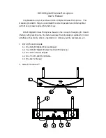
(2) Power Switch: Switches on/off the microphone (with status LED).
(3) Upper Housing: For easy holding the microphone, and to protect the wireless
transmitting PCB inside.
(4) Lower Housing: Protects the batteries from falling off.
(5) Rubber Cover: Protects the antenna and strengthen the transmitting effect.
Do not hold onto this area while using the microphone.
(6) Battery Compartment: Accommodates two AA batteries.
(7) Channel Switch: Changes the channel (total 16 channels) to eliminate
possible interferences.
(8) RF Power Switch: Adjusts the RF transmission power according to the practical
application.
3. Operating Instruction:
3.1.
Set Up the System:
3.1.1.
Plug the supplied DC adapter to a wall outlet and connect the output end
to the power receptacle on the Receiver.
3.1.2.
Press the Receiver
’
s power switch to turn the power on, and the status LED
will light up green.
3.1.3.
Press the microphone power switch to turn the power on, and the status
LED will light up green. When the Microphone Connecting LED on the
Receiver lights up red, it indicates the microphone signal is been received
by the Receiver.
3.1.4.
For best pickup result, keep the microphone to the sound mouth or source
in between 2 to 5 cm.
3.2.
Turn Off the System:
3.2.1.
Press on the microphone power switch till the status LED goes off. When
the microphone is been turned off, the Microphone Connecting LED on the
Receiver would also go off.
3.2.2.
Press on the Receiver’s power switch till the status LED goes off.
3.3.
Replace Batteries:
3.3.1.
When the microphone is on, but the status LED keeps blinking, it indicates
the battery energy is running low. Please replace the batteries.
3.3.2.
Turn the lower housing counter-clockwise to remove the lower housing as
shown in Figure 3.


