Carlton 3500D Owner'S Manual Download Page 49

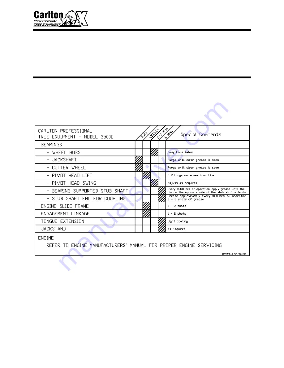
3500D                      LUBRICATION SCHEDULE


27


• 

The model 3500D, as well as all of our 
machines, is built to be a rugged performer.  
Your new machine is sturdy and our design 
goals are simplicity and reliability.


• 

A regularly scheduled maintenance 
program will pay big dividends in machine 
life, performance and avoided downtime. 


 Lubrication 

Schedule 


• 

USE TEXACO

®

 STARPLEX II GREASE.


Summary of Contents for 3500D

Page 1: ...__________ Engine Specification _____________ Engine Serial _____________ Purchase Date _____________ Dealer _____________ Carlton J P Carlton Company Div DAF Inc 121 John Dodd Road Spartanburg SC 293...

Page 2: ......

Page 3: ...L ENGINE EXHAUST WARNING CALIFORNIA Proposition 65 Warning Diesel engine exhaust and some of its constituents are known to the State of California to cause cancer birth defects and other reproduction...

Page 4: ......

Page 5: ...3500D SAFETY ALERT...

Page 6: ......

Page 7: ...3500D SAFETY ALERT...

Page 8: ......

Page 9: ...3500D SAFETY ALERT...

Page 10: ......

Page 11: ...3500D SAFETY ALERT...

Page 12: ......

Page 13: ...3500D SAFETY ALERT...

Page 14: ......

Page 15: ...be liable for consequential damages resulting from breach of warranty IT IS NECESSARY TO RETURN THE WARRANTY VALIDATION FORM AND NOTIFY J P CARLTON CO INC IN WRITING WITHIN TEN 10 DAYS FROM DELIVERY D...

Page 16: ......

Page 17: ...ned from the manufacturer It is the customers responsibility to deliver machine to dealers facility unless other arrangements have been agreed to between the selling dealer and the customer The manufa...

Page 18: ......

Page 19: ...top machine and remove key before performing any type of maintenance 4 ______ Customer has been warned not to operate the machine without the cutter wheel guard in place 5 ______ Customer has been fur...

Page 20: ......

Page 21: ...CE 22 LUBRICATION CHART 27 TROUBLESHOOTING GUIDE 28 WIRING DIAGRAM 30 LIGHTS BRAKES ASSEMBLY 34 SERVICING CUTTER WHEEL 37 SERVICING HYDRAULICS 42 SERVICING BOOM PIVOT 44 SERVICING BELTS 45 SERVICING B...

Page 22: ......

Page 23: ...experiment with the controls and gradually work yourself up to the full capabilities of this machine The Carlton Model 3500D is a durable and profitable professional stump grinder Read this manual Us...

Page 24: ...ut any prior notification or obligation Inspect your new Carlton Stump Grinder as soon as you receive it Any damages incurred during shipment are not warranted and therefore not covered repairs You sh...

Page 25: ...uards Optional hour meter Optional Key switch High quality epoxy primer Dupont Imron Finish Optional Remote control Double wire braid hydraulic hose Large fuel tank Large hydraulic oil reservoir High...

Page 26: ...g Height Above Ground 40 Cutter head Swing 80 arc Number of Teeth on Cutter Wheel 32 Cutter Wheel Diameter W Teeth 26 1 2 Cutter Wheel Thickness 1 Blanchard Ground Jack Shaft Bearings 1 11 16 Cutter W...

Page 27: ...3500D MACHINE SPECIFICATIONS 5...

Page 28: ...this symbol The Safety Alert Symbol will be accompanied by one of the following words DANGER WARNING or CAUTION A DANGER symbol means that if the instructions are not followed the possibility of serio...

Page 29: ...n while running or during transport Do not move position or transport this machine while cutter wheel is engaged DO NOT operate any machinery while under the influence of alcohol or drugs prescription...

Page 30: ...nded Stop engine and remove key when repairing or adjusting machine or drive belts Keep engine in good condition service as instructed in engine manual Do not touch engine while running or hot serious...

Page 31: ...on ground See Engine Assembly section for part numbers Check condition of tires Inflate to proper pressure Check wheel lug nuts Inspect towing hitch safety chains and towing lights Check condition an...

Page 32: ...wner s Manual for proper oil level HYDRAULIC CONTROLS A series of hydraulic controls are located on the machine and are clearly marked Lever 1 Cutter Wheel Lift Shown as CUTTER HEAD RIGHT LEFT on radi...

Page 33: ...rd the front of the machine It may be easier to lift the engine slide lock if you first press down on the engagement lever To disengage the cutter wheel reduce the engine RPM to idle and slowly push t...

Page 34: ...on the upper right hand side of the machine control panel Press and hold the Murphy By Pass while turning the key switch Run the engine a few minutes to allow the oil to circulate before starting to...

Page 35: ...ter remove the cover on the control box There are 3 bolts on each side Turn cover over and drill holes in the control box wall for attaching the radio control receiver make sure the hole locations mat...

Page 36: ...e by pass switch to start the machine If the engine doesn t start right away and you have to restart it turn the key switch OFF and back ON Make sure the light on the transmitter is still on and resta...

Page 37: ...eiver remove the cover from the machine control box Remove the radio receiver panel by unlatching the plastic tabs on either side of the receiver see the radio control manual included in this manual a...

Page 38: ...ostic list in the radio control manual Check the light configuration and compare it to the Receiver Diagnostic list in the radio control manual If status light on radio receiver is flashing red a fuse...

Page 39: ...ensure that the tongue of the stump grinder rides level or slightly down in the front A proper amount of tongue weight is required to allow machine to tow properly Too little tongue weight will result...

Page 40: ...with a remote or radio control transmitter Test controls for proper operation Avoid transversing slopes DO NOT OPERATE THE ENGINE AT AN ANGLE GREATER THAN 25 OR SEVERE ENGINE DAMAGE WILL OCCUR PROPER...

Page 41: ...obstructed movement Cutter head swing speed should be adjusted to a rate that will allow cutter wheel to pass through stump smoothly If jerking bouncing or significant drops in engine speed occur swin...

Page 42: ...to position machine closer to stump for next series of passes and continue cutting Continue in this manner until stump has been removed Larger stumps may require repositioning machine to work at best...

Page 43: ...h the portion of the cutter wheel shown NEVER UNDERCUT THE STUMP Undercutting the stump can cause severe kickback vibration and component damage NEVER CUT THE STUMP FROM THE TOP The cutter wheel will...

Page 44: ...MACHINE OTHERWISE SEVERE PERSONAL INJURY COULD OCCUR AS WELL AS MACHINE DAMAGE ALL MACHINE PARTS MUST COME TO A COMPLETE STOP AND HAVE TIME TO COOL COMPLETELY BEFORE SERVICING A MACHINE OR SEVERE INJ...

Page 45: ...is equipped with Citgo AW32 hydraulic oil at the time of manufacture To access the jackshaft bearings you will have to remove the jackshaft cover Check setscrews in jackshaft bearings and cutter wheel...

Page 46: ...attract dirt Grease engagement arm pivot weekly 2 places Use Texaco Starplex II grease Wipe off excess grease Excess grease will attract dirt Grease jackshaft bearings daily There is a cover on the j...

Page 47: ...of operation using Texaco Starplex II grease The grease fitting is easily accessible behind the V belt guard Apply grease using a hand held grease gun until the pin extends from the pressure relief va...

Page 48: ...Wipe off excess grease Excess grease will attract dirt Grease spindles every 2 to 3 months Spindles are easy lube type Remove rubber grommet and grease at grease fitting until grease is seen around g...

Page 49: ...is built to be a rugged performer Your new machine is sturdy and our design goals are simplicity and reliability A regularly scheduled maintenance program will pay big dividends in machine life perfor...

Page 50: ...ng Belt Squeal Belt tension too loose Belt out of alignment Tighten Align Pulleys Belt jumping off Engaging or disengaging belt at high engine RPM Belt keeper too far from belt Belt worn Pulley worn O...

Page 51: ...ring Bearing will not take grease Grease fitting clogged Replace fitting Cutter head swings faster one way than the other Counter balance valve is out of adjustment Cylinder bad Adjust counter balance...

Page 52: ...3500D MACHINE WIRING 30 STANDARD WIRING DIAGRAM...

Page 53: ...3500D MACHINE WIRING 31 REMOTE WIRING DIAGRAM...

Page 54: ...3500D MACHINE WIRING 32 REMOTE BOX WIRING...

Page 55: ...3500D MACHINE WIRING 33 RADIO WIRING DIAGRAM SEE RADIO CONTROL MANUAL INCLUDED IN THIS MANUAL FOR MORE...

Page 56: ...50140 1 4 20 x 3 4 HCS 4 4 0150218 1 4 20 Lock Nut 4 5 0350046 Breakaway Switch 1 6 3500163 Light Connector Bracket 1 7 0350050 1 Loom Clamp 3 8 0550211 Brake Drum w studs races 2 9 0350044 Tail Light...

Page 57: ...lever 1 2b 0550222 Right hand actuating lever 1 3 0550223 Anchor post washer 1 4 0550224 Wire clip 3 5 0550225 Retractor spring 2 6 0550226 Shoe lining kit 1 7 0550227 Adjuster assembly 1 8 0550228 A...

Page 58: ...3500D LIGHTS BRAKES ASSEMBLY 36 TRAILER LIGHTS BRAKES WIRING...

Page 59: ...TEETH PROPERLY INSTALLED EXCESSIVE MACHINE VIBRATION WILL OCCUR CAUSING PREMATURE BEARING FAILURE AND OTHER EQUIPMENT DAMAGE PLACE THE CUTTER WHEEL ON THE GROUND WHEN PERFORMING SERVICE ON A MACHINE...

Page 60: ...pockets carry like arrangements of teeth to cancel vibration Straight teeth are mounted in TWO OPPOSING OUTSIDE POCKETS A straight tooth must have a 45 tooth accompanying it in the same pocket set The...

Page 61: ...utter wheel in position during tooth removal and re installation The locking pin will only lock in the deep slots of the outer teeth Line the slot up with the locking pin slot and insert the pin to lo...

Page 62: ...g purposes only It does not refer to the left side of the machine as described in the General Information section Outside pocket teeth are Short Plow Bolt Bits These pockets are angled and welded in p...

Page 63: ...shank will hit the stump and not the carbide thus causing a lot of vibration Once the shank is angled far enough back then begin sharpening carbide Cut shank with a standard rock and cut carbide with...

Page 64: ...O NOT USE HAND OR FINGER ALWAYS WEAR EYE PROTECTION HYDRAULIC OIL FILTER Check hydraulic oil level daily with engine off and cool and replenish as necessary A site glass is provided for easy viewing I...

Page 65: ...ing down into position displacing old bushing in the process Swing cylinder back into position Re install rod end to mainframe using new pin assemblies REPLACING HYDRAULIC PUMP Engine must be shut off...

Page 66: ...vot monthly Do Not Over Grease There is a Pop Out Valve above the grease fitting if the pin pops out enough grease has been applied Wipe off excess grease Excess grease will attract dirt The boom pivo...

Page 67: ...COMPLETE STOP AND HAVE TIME TO COOL COMPLETELY BEFORE SERVICING A MACHINE OR SEVERE INJURY COULD OCCUR POSSIBLY SERIOUS BURNS AND OR DISMEMBERMENT PLACE THE CUTTER WHEEL ON THE GROUND WHEN PERFORMING...

Page 68: ...Check and adjust belt tension often when belts are new If any adjustment is required there is a linkage assembly below the engagement handle on the operator side Loosen jam nut and adjust clevis with...

Page 69: ...Replace V belt guard cover and tighten the bolts DO NOT RUN MACHINE WITHOUT ALL GUARDS IN PLACE AND SECURED GENERAL TENSIONING OF V BELT DRIVES Tensioning of belts on a V belt drive is usually not cri...

Page 70: ...CCUR CAUSING PREMATURE BEARING FAILURE AND OTHER EQUIPMENT DAMAGE Special care needs to be taken with your Poly Chain belt Alignment tension and cleanliness of this belt are very important The Poly Ch...

Page 71: ...hing for replacing the bushing and sprocket When the belt has been loosened remove the cutter wheel sprocket Remove the three screws in the bushing and then screw two of the screws into the two thread...

Page 72: ...l shaft and inside the sprocket Push the bushing as close to the position you marked earlier as possible Replace and tighten the screws Torque screws to 67 ft lbs Tighten the belt by sliding the jacks...

Page 73: ...ake only slight adjustments at a time and recheck tension repeat as necessary until tension is correct Then once the belt is adjusted tighten the front bolts against the bearing Recheck belt alignment...

Page 74: ...e bolts in the jackshaft bearings when the tension is adjusted properly Retighten the nuts on the bolts that are holding the belt guard to the machine Replace belt guard cover and bottom Tighten the b...

Page 75: ...3500D SERVICING BELTS 53 Replacing Poly Chain Belt...

Page 76: ...NS AND OR DISMEMBERMENT PLACE THE CUTTER WHEEL ON THE GROUND WHEN PERFORMING SERVICE ON A MACHINE In all Carlton model Stump Grinders you will find link belt bearings that are made to be purged with g...

Page 77: ...te this measurement down After the belts have been removed remove the jackshaft sprocket Remove the two screws in the bushing and then screw one of the screws into the threaded hole to push the bushin...

Page 78: ...s down do not tighten all the way down you will need to move them later to adjust belt tension Replace the Poly Chain guard and replace the bolts washers and nuts that were removed earlier Tighten the...

Page 79: ...he Poly Chain belt DO NOT ADJUST THE BELT TENSION AT THIS TIME The cutter wheel sprocket will be replaced when replacing the belt Line up Poly Chain sprockets using a straight edge Slide shaft through...

Page 80: ...essary until tension is correct Then once the belt is adjusted retighten the bolts on the other side of the bearings Recheck belt alignment after tightening all bolts and nuts to make sure the belt is...

Page 81: ...en Do this for all four setscrews This will help prevent shaft from spinning and walking inside of bearing Finish tightening the nuts on the carriage bolts holding the Poly Chain belt guard in place R...

Page 82: ...E A MACHINE WITHOUT A COMPLETE SET OF TEETH PROPERLY INSTALLED EXCESSIVE MACHINE VIBRATION WILL OCCUR CAUSING PREMATURE BEARING FAILURE AND OTHER EQUIPMENT DAMAGE PLACE THE CUTTER WHEEL ON THE GROUND...

Page 83: ...facing inward toward the cutter wheel There are two setscrews in each bearing lock collar Tighten one setscrew in each collar and remove the other setscrew Punch a start point in the shaft and drill...

Page 84: ...to SERVICING BELTS section for proper installation and tensioning of all belts Alignment and tension of Poly Chain belt is very important See information on alignment using straight edge in Replacing...

Page 85: ...N A MACHINE The most service you should have to do for the bearing supported stub shaft is to grease it properly The bearing grease fitting is easily accessible behind the v belt guard Another grease...

Page 86: ...ly easier Remove the bolts holding the belt guard onto the machine and remove the belt guard Then remove the engine sheave Remove the bolts in the engine sheave bushing and screw them into the extra t...

Page 87: ...rom the stub shaft plate and slowly screw them in until the plate breaks loose Leaving a couple of bolts screwed in slightly may help to keep the assembly from dropping when separated from the engine...

Page 88: ...erted and lightly tightened torque all bolts to 35 ft lbs Put anti seize coupling lubricant on the inside of the coupling Line up external splines with the coupling ID and slide the stub shaft plate i...

Page 89: ...eaves Torque the bolts in the sheaves to 30 ft lbs Be sure to bolt the belt keepers onto the stub shaft plate before you put the engine sheave on it will be easier that way Replace the v belt and alig...

Page 90: ...mp mp 90 1 9 0300218 3 4 mp jic 90 1 10 0300234 3 4 jic orb 1 11 0300245 1 2 mp 5 8 orb 90 1 12 0300205 3 8 orb jic 90 1 13 0300236 1 2 orb jic 1 14 0300217 1 2 jic 3 4 mp 90 1 15 0300237 3 8 orb jic...

Page 91: ...3500D HYDRAULIC ASSEMBLY 69 REMOTE CONTROL HYDRAULIC ASSEMBLY...

Page 92: ...NO PART NO DESCRIPTION QTY 1 0300150A Aluminum Manifold Block 1 2 0300150AB Solenoid Valve DO3 3 3 0300150AA Swing Speed Control Cartridge 1 4 0300120A Counter Balance Cartridge Valve LKN 3 5 Relief...

Page 93: ...14 3 8 mp jic 90 4 19 0300259 3 8 mp jic jic tee 2 20 0300215 3 8 jic 1 2 mp 90 6 21 0300231 1 2 mp 3 8 mp 1 22 0300122 Valve Body ECB 1 23 0300213 1 4 mp 3 8 jic 90 1 24 0300224 1 2 mp fp fp tee 1 25...

Page 94: ...3500D HYDRAULIC ASSEMBLY 72 SWING OUT CONTROLS HYDRAULIC ASSEMBLY...

Page 95: ...05E ITEM NO PART NO DESCRIPTION QTY 1 Body Assembly 1 2 Lock Nut 1 1 4 12 1 3 Crown Seal 1 4 Piston 1 5 O Ring 1 6 Piston Rod 1 7 O Ring 1 8 Bu Washer 1 9 Square Retaining Ring 1 10 U Cup 1 11 End Cap...

Page 96: ...0105D ITEM NO PART NO DESCRIPTION QTY 1 Body Assembly 1 2 Lock Nut 1 14 1 3 Crown Seal 1 4 Piston 1 5 O Ring 1 6 Piston Rod 1 7 O Ring 1 8 Bu Washer 1 9 Square Retaining Ring 1 10 U Cup 1 11 End Cap 1...

Page 97: ...y 1 2 0150222 Lock Nut 1 14 1 3 0300164 Piston Ring 1 4 0300151 O Ring 2 5 0300166 Bu Washer 1 6 0300161 Piston 1 7 0300149 O Ring 1 8 0300090 Piston Rod 1 9 0300169 Bu Washer 1 10 0300163 Snap Ring 1...

Page 98: ...3 0300172 Snap Ring 1 4 0300173 Front Plate 1 5 0300174 Back Plate 1 6 0300175 Bearing Case Assembly 1 7 0300176 Pump Body 1 8 0300177 Drive Gear 1 9 0300178 Idler Gear 1 10 0300179 Washer 4 11 12 03...

Page 99: ...22 3500177 Front Chip Guard 1 23 3500191 Chip Guard Front Bracket 2 24 3500192 Chip Guard Side Bracket 3 25 0150117 3 8 16 x 1 Carriage Bolt 32 26 0150303 3 8 Flat Washer 34 27 0150207 3 8 Lock Nut 3...

Page 100: ...3500D FRAME ASSEMBLY 78 BASE FRAME ASSEMBLY...

Page 101: ...350028 Circuit breaker 40 Amp 1 9 0350029 Junction Box Fused 1 10 0350030 Junction Box Terminal 1 11 3500232 Control Box Cover 1 12 3500280 Control Box Flap 1 13 0150145 3 8 16 x 6 HCS 3 14 0150404 3...

Page 102: ...3500D FRAME ASSEMBLY 80 REMOTE BOX ASSEMBLY...

Page 103: ...olt 7 7 0150303 3 8 Flat Washer 7 8 0150207 3 8 16 Lock Nut 7 9 0300130 Control Valve 1 10 0150103 3 8 16 x 1 HCS 5 11 0150404 3 8 Lock Washer 5 12 0350031 Hour Meter Datcon 1 13 3500276 Control Box B...

Page 104: ...300138 Cylinder Pin 1 8 18 0150123 5 16 18 x 3 4 SHCP 6 19 0150124 5 16 18 x 3 4 FHSCP 6 20 0150308 1 Flat Washer 4 21 0150801 Hardened Bushing 1 6 22 A160T07 Key 3 4 x 3 4 x 3 2 23 3500162 Side Pivot...

Page 105: ...3500D PIVOT ASSEMBLY 83...

Page 106: ...4 HCS 4 4 1 2 Lock Washer 4 5 4100120 Belt Engagement Handle 1 6 0150501 Cotter Pin 3 16 x 2 1 7 4100154 Linkage Assembly 1 8 0150603 Clevis Pin 1 2 x 1 3 8 2 9 Cotter Pin 1 8 x 1 3 8 2 10 4404110 Eng...

Page 107: ...2 USS Flat Washer 1 19 0150303 3 8 SAE Flat Washer 6 20 050062 Stub Shaft Coupling Plate 1 21 10 MM 1 5 x 20 MM HHCS 8 22 10 MM Lock Washer 23 23 050061 Bearing Supported Stub Shaft 1 24 10 MM 1 5 x 3...

Page 108: ...itting is on top of the stub shaft assembly before bolting the stub shaft plate into place as illustrated in the Servicing Stub Shaft Section of the manual Remove the grease fitting on the new stub sh...

Page 109: ...500185A Jackshaft 1 11 16 1 2 0500113 Link Belt Bearing 1 11 16 2 3 5 8 11 x 3 HCS 4 4 0150305 5 8 Flat Washer 8 5 0150216 5 8 11 Lock Nut 4 6 Key 3 8 Square x 2 5 8 1 7 Key 3 8 Square x 3 3 4 1 8 1 2...

Page 110: ...0150303 3 8 Flat Washer 9 7 0150404 3 8 Lock Washer 9 8 0150207 3 8 16 Lock Nut 9 9 0250115B Jack Shaft Sprocket Taper Lock 1 10 0250115G Taper Lock Bushing 1 11 16 1 11 0250115M Taper Lock Bushing 2...

Page 111: ...5 8 11 Lock Nut 9 10 3500197 Shaft Washer 1 11 0150106A 1 2 13 x 1 1 2 HCS 4 12 0150304 1 2 Flat Washer 8 13 0150206 1 2 13 Lock Nut 4 14 3500236 Boom Chip Guard 1 15 3 4 10 x 6 HCS 1 16 0150118 3 8 1...

Page 112: ...3500D CUTTER WHEEL ASSEMBLY 90...

Page 113: ...urbo 60 Diesel 15 43 70 arc 32 26 5 1 N A 4 300 SP8018 TRX Track Mounted Deutz Turbo 78 Diesel 18 43 80 arc 32 26 5 1 N A 5 420 HURRICANE RS Track Mounted John Deere Turbo 140 Diesel 25 53 360 48 31 1...

Page 114: ......

Page 115: ......

Page 116: ......

Page 117: ......

Page 118: ......

Page 119: ......

Page 120: ......

Page 121: ......

Page 122: ......

Page 123: ......

Page 124: ......

Page 125: ......

Page 126: ......

Page 127: ......

Page 128: ......

Page 129: ......

Reviews: