Motor Controllers AC Variable Frequency Drives
RVBS
Specifications are subjected to change without notice.10/08/2021
22
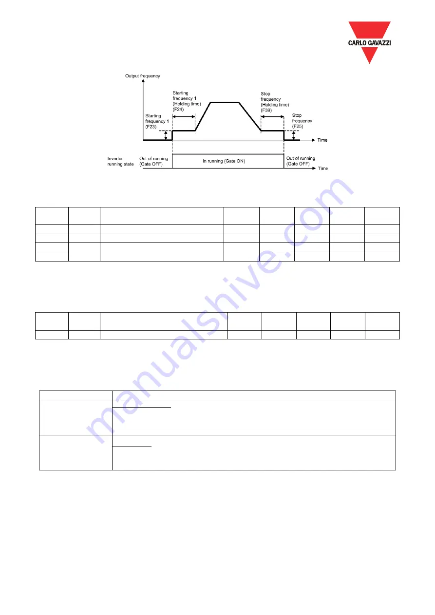
< Speed profile applying start/stop function >
Function
Code
Mod.
add.
Description
Def
Min
Max
U.M.
R/W
F18
0x0012
Starting Frequency1
10
1
600
0.1Hz
R/W
F19
0x0013
Starting Frequency1 (Holding time)
0
0
1000
0.01Sec.
R/W
F20
0x0014
Stop Frequency
2
1
600
0.1Hz
R/W
F23
0x0017
Stop Frequency (Holding time)
0
0
1000
0.01Sec.
R/W
4.2.5
Motor sound
F21 allows to set the motor sound corresponding to carrier frequency.
Function
code
Mod.
add.
Description
Def
Min
Max
U.M.
R/W
F21
0x0015
Motor Sound (Carrier frequency)
4
2
10
kHz
R/W
4.2.6
Deceleration mode
H06 specifies the deceleration mode to be applied when a run command is turned OFF.
Data for H06
Function
0
Normal deceleration
The inverter decelerates and stops the motor according to deceleration commands specified by
H04 (Acceleration/deceleration pattern), F08 (Deceleration time 1), and E09 (Deceleration time
2).
1
Coast-to-stop
The inverter immediately shuts down its output, so the motor stops according to the inertia of the
motor and machine and their kinetic energy losses.
➢
When reducing the reference frequency, the inverter decelerates the motor according to the
deceleration commands even if H06 = 1 (Coast-to-stop).
Setting the H13 data to "1" (ON) enables forced brake control. If regenerative energy produced during
deceleration of the motor and returned to the inverter exceeds the inverter’s braking capability, an
overvoltage trip will occur. The forced brake control increases the motor energy loss during deceleration,
increasing the deceleration torque.


