MN90200A 090117
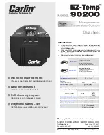
Model 90200A and G Microprocessor Temperature Controls — Data sheet
Mounting –
90200A and G controls mount to any standard well.
Mount the 90200A & G directly to a well (new or existing) with
hardware supplied in the separate well mounting kit.
Well Kits –
Wells for 90200A and G sensors are available in the
sizes shown below. Well kits include sensor mounting hard-
ware designed to hold sensor securely in position.
Sensors –
Sensors are available separately for the 90200A and G.
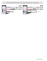
Configurations
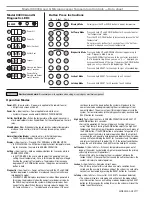
Error Codes
3"
4
3
/
8
"
4
3
/
4
"
Error Code
Reason
01
Primary (K2) relay is welded on.
Note:
If the control is reset
from error code 01, the red LED will flash every 5 seconds
indicating the control must be replaced.
02
Primary & Safety relays (K1 and K2) on. The control cannot
be reset from error code 02 and must be replaced.
03
Primary & Safety relays (K1 and K2) are off.
Note:
If this
error is detected, the control will show error code
03
and
enter soft lockout two times to try and resolve the issue. If
the problem persists the control will enter hard lockout.
05
Simulated High Temp lockout
06
Temp is above set high temp but below thermistor high
(250°F)
Error Code
Reason
20
Temp sensor 1 out of range failure
21
Temp sensor 2 out of range failure
22
High limit temp sensor out of range failure
23
Temp sensor 1 pin is open
24
Temp sensor 2 pin is open
25
High limit temp sensor is open
10
,
1 1
,
12
,
13
,
14
,
15
Internal hardware safety failure – unit should be replaced. Contact customer service for additional informa-
tion. 1-800-989-2275


