Carlin 702GAS Instruction Manual Download Page 1

126 Bailey Road 

North Haven, CT 06473

Ph  203-680-9401 

Fx  203-680-9403

C a r l i n   C o m b u s t i o n   Te c h n o l o g y

T

ech


support

   800-989-2275

carlincombustion.com

©


Copyright 2020 — Carlin Combustion Technology

  Except where specifically stated otherwise, this manual 

must be used only by a qualified service technician.


In the state of Massachusetts, this product must be 

installed by a licensed Plumber or Gas Fitter.


Failure to comply with the above or other requirements 

in this manual could result in severe personal injury, 

death or substantial property damage.


USER

 — Refer only to User care and maintenance 

on back page for information regarding operation of 

this burner. The burner Instruction Manual is intended 

only for your service technician. The burner and heat 

exchanger must be inspected and started at least an-

nually by your service technician.

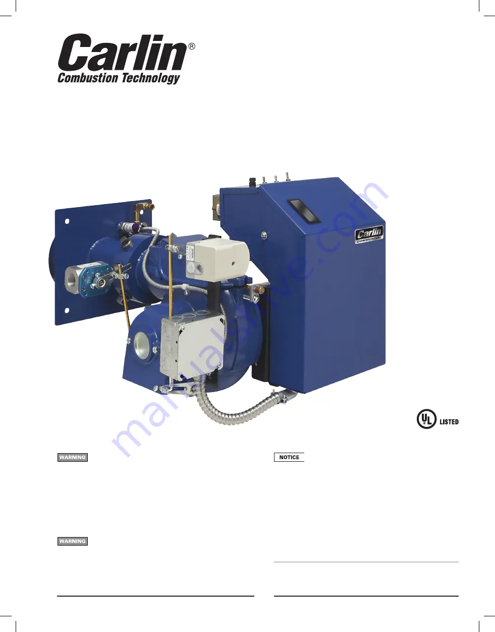
  Check burner cartons carefully. The Model 702GAS 

combination gas burner was assembled and tested at 

the factory before shipment. If the burner was ordered 

with a completed assembled gas train, the train was 

pressure tested and electrically checked for proper 

operation. Where possible, the gas train or components 

were shipped in the same carton as the burner. Check 

your packing slip for the number of cartons shipped 

from the factory.

MODEL


702GAS

Low-High-Low Step Modulating

840 to 1600 MBH Gas

(High-fire input capacities)

Instruction Manual

Summary of Contents for 702GAS

Page 1: ...maintenance on back page for information regarding operation of this burner The burner Instruction Manual is intended only for your service technician The burner and heat exchanger must be inspected a...

Page 2: ...heguidelinesbelowtoavoidpotentialsevere personal injury death or substantial property dam age Installer service technician Read all instructions before proceeding Perform all procedures and in the ord...

Page 3: ...mply with the latest editions of Installation of Domestic Gas Conversion Burners ANSI Z21 8 National Fuel Gas Code ANSI Z223 1 NFPA 54 National Electrical Code ANSI NFPA 70 All additional applicable n...

Page 4: ...into the burner through a manifold around the air tube The gas then circulates through a set of four orifice spuds into the air stream upstream of the retention ring The spin of the air flow at the re...

Page 5: ...0 Btuh of all appliances in the space Do not install or operate the burner if any component is dam aged or if burner does not comply with other guidelines of this manual and the appliance manual Inspe...

Page 6: ...u facturer s instructions Wire the switch into the appliance limit circuit to shut off the appliance burner if sustained downdraft should occur Refer to the appliance manufacturer s instruction manual...

Page 7: ...2 Metal louvers or grilles free area area times 0 60 3 Screens when used must be no smaller than inch mesh Motorized vent dampers Wire the vent damper end switch to prevent operation of the burner un...

Page 8: ...ications Whenfiringwithpositive overfire pressure do not exceed the pressure specified in the appliance manual Positive overfire pressure reduces maximum burner capacity See Page 3 for estimated reduc...

Page 9: ...e a floor liner when possible The floor liner will improve firing in most applications Extend floor liner 3 to 4 inches up the side walls 4 Target wall liners Extend target wall liners at least 3 to 4...

Page 10: ...ance opening so the end of the air tube is flush with or slightly short of the inside surface of the combustion chamber 4 Place gasket onto boiler front plate 5 Slide the end of the air tube into the...

Page 11: ...enough ventilation to prevent overheating of the appliance burner and controls If there is risk of overheating you must install ventilation air openings sized large enough to provide air for cooling t...

Page 12: ...e terminal strip inside the gas train J box b See the label in the burner junction box included Gas valve vent opening The V48 diaphragm gas valve is NOT fitted with a vent limiting orifice in the ven...

Page 13: ...be more than the gas pressure at the burner gas train en trance minus 3 4 w c pressure required at entrance to butterfly valve See Figure 6 for gas train pressure drop information The standard gas tra...

Page 14: ...990 810 690 620 2 2 750 1 900 1 520 1 300 1 150 2 4 350 3 000 2 400 2 050 1 850 Note 1 For natural gas with specific gravity other than 0 60 consult National Fuel Gas Code for correction factor PROPAN...

Page 15: ...rmation for burner equipped with a primary control not covered in this manual see Figure 7A for a legend to callouts Turn off power to appliance when servicing burner Failure to comply could result in...

Page 16: ...steam boiler activated Read the appliance manual for the location of the high fire control when used 3 See Figures 7 and 8 to connect the high fire control to the burner firing rate circuit 4 The burn...

Page 17: ...nuals and wiring diagrams Gas manifold spud orifices sealed with pipe dope and tight Gas lines in good condition sized and designed correctly Gas line connections and fittings tight Burner appliance a...

Page 18: ...et air damper linkage Table 5 Initial burner settings see the pages 18 through 22 for final adjustments using test instruments 6 Set burner initial head and damper positions continued 3 4 Determining...

Page 19: ...e the maximum burner firing rate is reduced The firing rate is also reduced for altitudes higher than 2000 feet above sea level See page 3 for rating information 3 Adjust the burner fuel and air setti...

Page 20: ...personal injury death or substantial property damage 3 Check the flame signal after the pilot has shut down to ensure the signal is still strong with main flame on 4 Move the burner fuel selector swi...

Page 21: ...ly valve indicator until it is at 90 Disengage actuator motor Rotate linkage to high fire Tighten the two hex head screws while still holding the motor linkage arm in high fire Rotate linkage to low f...

Page 22: ...ion with exhaust fans or other conditions operating 7 Adjust the burner using test instruments continued Combustion ventilation air Verify combustion ventilation air openings are not and will not be o...

Page 23: ...s valves before disconnecting any portion of fuel lines and before cleaning or removing any parts from the burner or related equipment Burner and appliance components can be extremely hot Allow all pa...

Page 24: ...season and to verify user is aware of proper operation and care of the burner appliance Review proper operation of the appliance burner unit with the user Turn off power to appliance Remove combustion...

Page 25: ...Btuh Manifold gas pressure IWC High fire Low fire Inlet gas pressure IWC CO2 Gas Low Fire ______ Gas High Fire ______ Gas Low Fire ______ Gas High Fire ______ O2 Were limit controls tested Comments ab...

Page 26: ...4 Combustion Head Assembly for 702GAS 7 4180002FS Gas Ignitor 8 35824S Motor Contactor 20 AMP R4242B1005 not shown ITEM PART NO DESCRIPTION 9 35311S C7027A1023 UV Scanner 97656S Q7800B1003 Sub Base 99...

Page 27: ...appliance burner unit NEW PHOTO TO COME ITEM PART NO DESCRIPTION 16 35824S Motor Contactor 20 AMP R4242B1005 19 EMX51UVS EMX51UV KIT includes all of the below 35311S C7027A1023 UV Scanner 97656S Q780...

Page 28: ...MN702GE 060320 28 10 Dimensions Figure 14 Dimensional data...

Page 29: ...MN702GE 060320 29 10 Dimensions continued Figure 14A Dimensional data angled gas train...

Page 30: ...and liquids Do not obstruct the flow of combustion and ventilating air Most motors currently used on residential type burners use permanently lubricated bearings and do not require field lubri cation...

Reviews: