Model 702G/O Advanced gas/oil burners — Instruction manual
Carlin part number MN702GO Rev. 06/23/14
– 11 –
Where appliance instructions differ from this manual, follow the appliance instructions.
5.
Slide the flame scanner sight pipe assembly forward until the 3/8" pipe
fits against the retention ring assembly. Then tighten the 1/8" Allen screw
to secure the tube in place.
6.
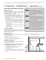
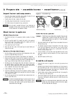
Check the electrodes and reposition if necessary. Position the electrodes
as shown in Figure 5. These settings are critical in ensuring a reliable
ignition.
7.
Once the electrodes are set, check all clamps to be sure they are securely
tightened.
8.
Insert the combustion head/nozzle assembly into the burner and secure
in place. See instructions on page 24.
Figure 5
Electrode settings
Inspect components and wiring
• Visually inspect all burner components and wiring.
• Verify that wiring is intact and leads are securely connected.
• Verify that all burner components are in good condition.
Install gas train on burner
1. The standard burner gas train is shipped fully assembled, with the piping
disconnected at the gas train unions. See separate instructions if installing
an optional knocked down gas train. The gas train is available in either
an angled (standard) or straight (optional) configuration.
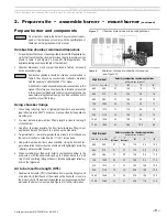
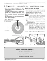
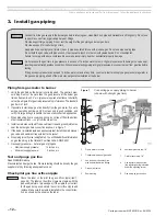
2. Connect the main and pilot gas trains at the unions (Figure 6).
To avoid damage to gas train components, do not hold compo-
nents with a pipe wrench or overtighten. Use only a crescent
wrench or other means. Failure to comply could result in severe
personal injury, death or substantial property damage.
3. Connect the flexible conduit, pre-attached to the burner J-box, to the gas
train J-box, and attach the wires to the terminal strip inside the gas train
J-box.
a.
Match wire colors of the incoming wires to those pre-wired to the terminal
strip inside the gas train J-box.
b.
See the label in the burner junction box or the wiring diagram on page 17.
Gas valve vent opening — The V48 diaphragm gas valve is
NOT fitted with a vent limiting orifice in the vent connection.
If local codes require, install piping from the vent connection
to outside, sized and installed as required by codes. Because
this is a diaphragm-assisted solenoid valve, a small amount of
gas will exit from the vent orifice each time the valve opens.
Figure 6
Gas train installation (shown with straight gas train)
2. Prepare site • assemble burner • mount burner
(continued)


