Carlin 51300S Installation Instructions & Operating Manual Download Page 1

1

Installation Instructions 

and Operating Manual

126 Bailey Road 

North Haven, CT 06473

Phone  203-680-9401 

Fax  203-680-9403

Carlin Combustion Technology

T

ech


support

  800-989-2275

carlincombustion.com

©


Copyright 2022 – Carlin Combustion Technology

Patent No. 11,428,407
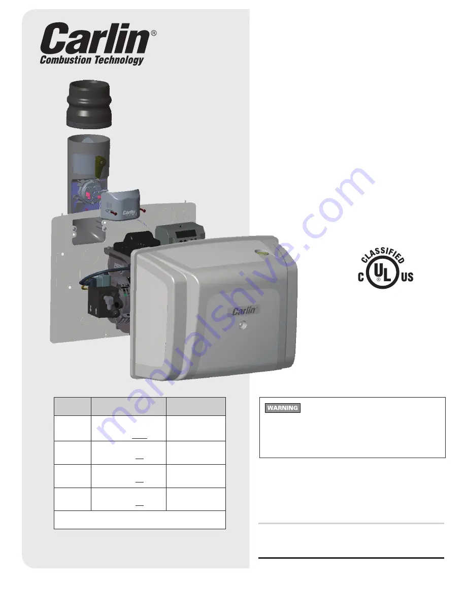
CAP

System Kit

Combustion 

Air Proving Kit with 

Burner Cut-Off

Designed to meet NFPA31*  

requirements for combustion air

CAP 

Model 

Description 

Firing Rate (GPH) 

51300S

Complete  

CAP System Kit

(for Carlin burners without covers) 

0.50 - 2.00

51300AS

Low Rate CAP Kit

(for Carlin burners with covers)

0.50 - 1.00

51300BS

Medium Rate CAP Kit

(for Carlin burners with covers)

1.05 - 1.45

51300CS

High Rate CAP Kit

(for Carlin burners with covers)

1.50 - 2.00

Note: All CAP System models require Carlin 70200  

Primary Control manufactured after Sept. 2018

*See Section 5.4.3.3 as covered by April 2019 TIA 16-2

 Electrical shock hazard. To prevent electrical 

shock, death, or equipment damage, disconnect power sup-
ply before installing or servicing CAP System. Only qualified 
personnel may install or service the CAP System in accor-
dance with local codes and ordinances. Read instructions 
completely before proceeding.

Summary of Contents for 51300S

Page 1: ...hout covers 0 50 2 00 51300AS Low Rate CAP Kit for Carlin burners with covers 0 50 1 00 51300BS Medium Rate CAP Kit for Carlin burners with covers 1 05 1 45 51300CS High Rate CAP Kit for Carlin burner...

Page 2: ...C A P S Y S T E M K I T C O M P O N E N T S s e e p a g e 3 f o r p a r t d e s c r i p t i o n s 8 13 9 1 14 17 18 20 15 19 16 2 12 3 6 7 4 5 10 11 10a 10b 10c 1b 1a 19a COMPONENTS CONTAINED IN POLYB...

Page 3: ...ssembled with CAP System Air Inlet above 10a 24 inch Air Flow Switch Wiring Harness 51308A 1 10b 10 14 x 1 2 Phillips Head Screw 50605 2 10c 8 16 x 3 4 Phillips Head Screw 51327 1 11 Connecting Flange...

Page 4: ...the burner cover backplate 2 5 REMOVE AIR INLET KNOCKOUT Remove the 2 x 4 air inlet knockout that corresponds to the desired air inlet position vertical or horizontal as shown in step 8 Pressure Swit...

Page 5: ...kplate 2 Secure the filler plate 19 below the burner air tube using the two 5 16 bolts and star washers 14 provided Install the 1 62 split grommet 17 around any BX cable wiring harness etc leaving the...

Page 6: ...em air inlet 10 onto the 2 x 4 air inlet knockout removed in Step 5 Mounting examples below 9 Slide the connecting flange 11 onto the air inlet 10 until fit is tight Reverse flange when using galvaniz...

Page 7: ...ng the cover 14 CHECK BURNER SETUP CAP System utilizes outside air for combustion Incoming air temperature will fluctuate by season which can significantly impact combustion Use the table below to set...

Page 8: ...components in the Burner Seal Kit see Step 6 Make sure that the burner cover screw 1b is tight This also prevents basement air from entering the cover Check that the correct air pressure switch 3 4 5...

Reviews: