


Electronics (Replace Components)
DPM IV
24
Service Instructions
05.19
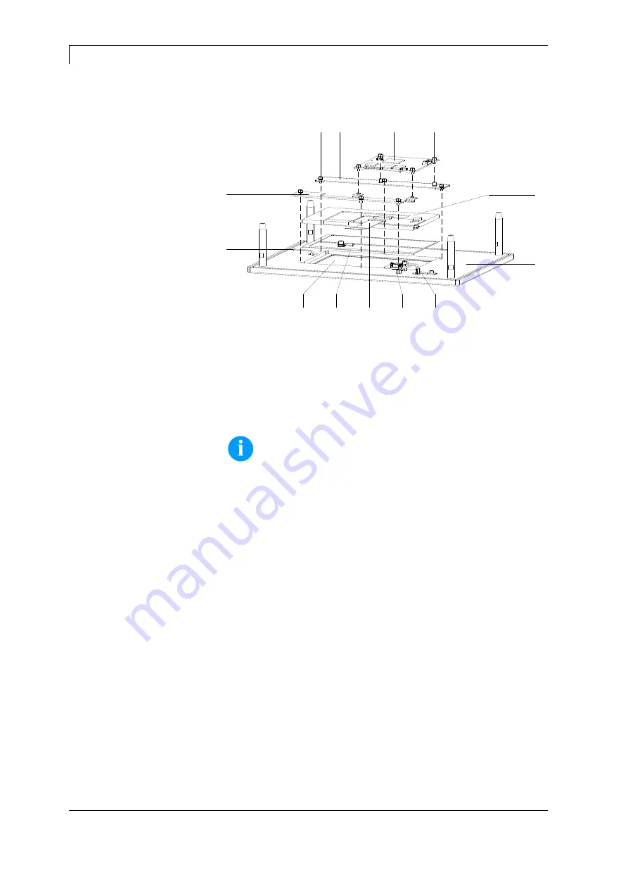
4.7 HMI Components
A
F
M
L
I
K
J
B
E
H
D
C
G
Figure 12
1. Unplug the control unit from the electrical outlet.
2. Unscrew the four screws on the rear and remove the front plate
(B) (see chapter 4.1, page 17). Disconnect all connecting cables
at the plug-in connectors while removing the front plate.
NOTICE!
During subsequent work, take care of a dust-free atmosphere in
order to bring no unwanted particles in the field of view of the
display.
3. Carefully remove the FFC cable (E) from the plug-in connector of
the CPU HMI (L).
4. Carefully remove the connection line (H) of touch panel from the
plug-in connector of CPU HMI (L).
5. After removing the connection cable to CPU and removing the
four screws (M), remove the CPU HMI (L).
6. Remove the six screws (J).
7. Lift the top display bar (K) and the bottom display bar (I).
8. Remove the graphic module (A) and the seal (F) from the
depression.
9. The touch panel (G) laminated onto the transparent keyboard is
visible now. The touch panel is interchangeable only in
combination with the transparent keyboard.
10. After careful loosening of the connecting cable (C) and removing
the screws positioned directly next to the cable, remove the
connection board (D) for the transparent keyboard.
Removing HMI
components
Summary of Contents for DPM IV
Page 1: ......
Page 16: ......
Page 26: ...Electronics Replace Components DPM IV 26 Service Instructions 05 19 ...
Page 60: ...Mechanics Replace Components DPM IV 60 Service Instructions 05 19 ...
Page 64: ...Cleaning DPM IV 64 Service Instructions 05 19 ...
Page 83: ...DPM IV Wiring Plans 05 19 Service Instructions 83 9 Wiring Plans 9 1 Control Unit Figure 45 ...
Page 84: ...Wiring Plans DPM IV 84 Service Instructions 05 19 9 2 Print Mechanics Left Version Figure 46 ...
Page 85: ...DPM IV Wiring Plans 05 19 Service Instructions 85 9 3 Print Mechanics Right Version Figure 47 ...
Page 86: ...Wiring Plans DPM IV 86 Service Instructions 05 19 ...
Page 90: ...Pin Assignment of Control Unit DPM IV 90 Service Instructions 05 19 ...
Page 95: ......
Page 96: ......


