


6
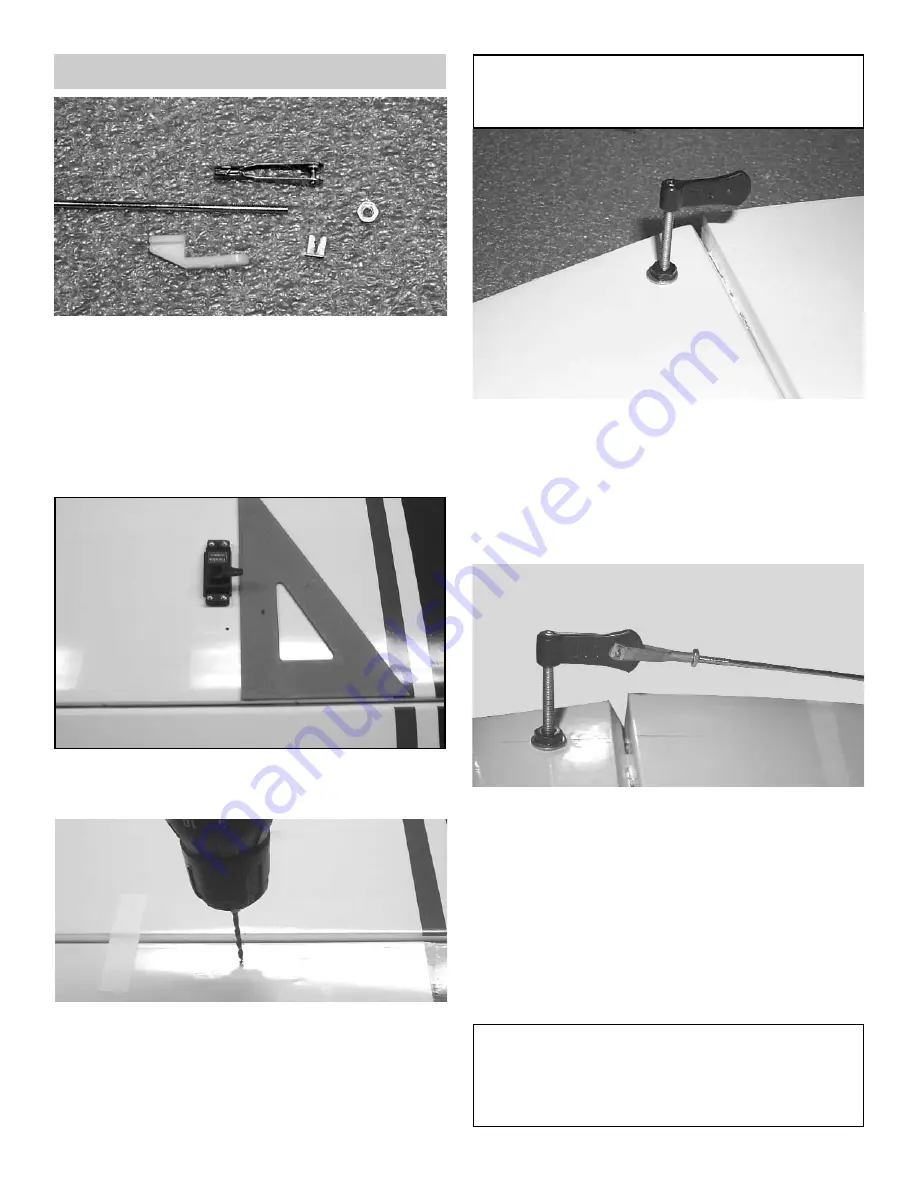
2.
With the aileron servo in place, make a mark
at a 90º degree angle to the trailing edge and
in line with the servo arm.
3.
Position the control horn bolt so that it is 3/4”
back from the hinge line on the mark that you
just made.
4.
Using a 9/64" drill bit, make a hole in the
aileron through to the top side.
5.
Insert the 6-32 x 2” screw from the top through
the aileron.
Place the #6 washer and the 6-32 hex nut on
the bolt and tighten. Make sure that you use
thread lock on the bolt and nut.
Screw the black adjustable horn bracket on
the bolt. Keep the hex nut tight.
6.
Thread on to the end of the 2-56 x 4-7/8”
pushrod a 2-56 nut and a 2-56 metal clevis.
Mount the clevis onto the black horn bracket
and secure using a metal clevis clip.
Measure the length of the pushrod to the
servo arm hole and make a 90 degree bend.
Mount the swivel keeper on to the wire and
clip in place.
Repeat the above steps for the remaining
aileron and flaps.
AILERON CONTROL HORN INSTALLATION
1.
Collect the following items
(4) Metal Clevis
(4) 4-40 Hex Nut
(4) 2-56 x 4-7/8" Threaded wire
(4) 6-32 x 2” Bolt
(4) 6-32 Hex nut
(4) #6 Washer
(4) 6-32 Black Horn Bracket
(4) Nylon Swivel keepers
HINT: Drill the hole from the bottom half way.
Then measure and mark the top of the
aileron and drill down to the hole from the
top of the aileron.
Caution:
Make sure each snap link is fully closed with a
clevis clip before and after each flight.