Servo Choice
The milled composite rudder tray is designed
for 3 JR servos (8511/8611) or better. If using
Futaba you can also fit the large S9152 ser-
vos, although you will need to sand about
2mm from the edges of the servo rails.
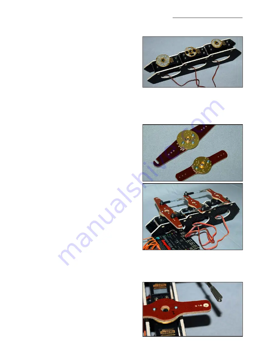
Fit the 3 rudder servos into the tray, with the
output shafts nearest to the tailplane, and
screw into position using the 2.9mm Ø x
13mm long sheet-metal screws supplied.
Servo arms
The supplied phenolic rudder servo output
arms
must
be bolted to 1” or 1.25” diameter
metal servo output discs. We used ‘Hangar 9’
# 3520’s. Please do
not
use the standard
plastic discs for this, as there is a chance that
the internal plastic splines can be stripped by
the current hi-torque servos - causing instant
rudder flutter, and probable loss of your plane.
Fit 3 metal output discs to the servos, and
rough sand the top surfaces of the metal discs
and the underside of the phenolic arms.
Centre the servos with your R/C, and then
glue the phenolic arms onto the discs with
epoxy, aligning them carefully so that they are
exactly parallel and at 90 degrees to the sides
of the tray in the neutral position. Make sure
that the slots are facing forward on the rear
phenolic arm.
When the glue has cured drill thru’ the arms
and discs and secure with 2 of the M2 bolts
and nuts on the front 2 servos, and 3 bolts for
the rear arm.
Make up the linkages from the hardware sup-
plied, joining the servos together as shown
with the threaded rods, ball-links and steel
clevises. Enlarge the holes in the phenolic
arms to Ø 3mm where the ball-links are
secured with the M3 x 16mm bolts and stop-
nuts. Fit just one of the linkages between the
phenolic arms at a time, and adjust the length
of the linkage very carefully until so that there
is minimal buzzing or humming from the ser-
vos at idle, and at full throw. When satisfied,
add the next linkage and follow the same
method of adjustment.
Composite-ARF YAK 55SP
(3m span)
18
(above) Centre the servos with the R/C, and bolt
the metal discs to the servos. Rough sand top
surface before gluing on the phenolic arms.
(below) You must bolt the phenolic arms to
metal servo output discs, using the M2 bolts and
nuts provided.
(above) Completed rudder servo tray.
(below) Sand small rounded dimples about
0.5mm deep for proper clearance of the M3
steel clevises,
only
on one side of each pheno-
lic horn, as shown here.


