9
ENG
MC DUCT +03U400025 - rel. 4 - 20201201
Step 2: Plan system layout
(Assistance is available from CAREL USA)
The MC atomizing heads discharge a plume of mist that will
reach 15 feet long and 3 feet in diameter in still air. In air handlers,
air passing over the heads will turn and carry the droplets, so it
is usually advantageous to have the atomizing heads discharge
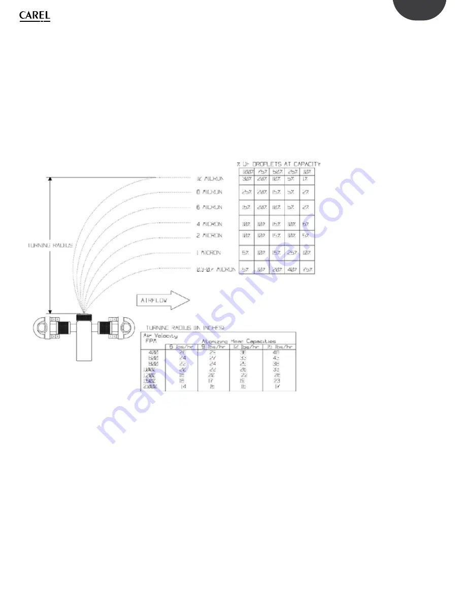
somewhat perpendicular to the air flow. The following graphic
illustrates that the lightest droplets turn first and the heaviest
droplets last, usually arriving at about the same evaporation
distance downstream. The TURNING RADIUS table shows how
high the air handler must be to avoid impingement.
This graphic also shows the mix of droplets contained in the
atomized mist at various levels of modulation. Accordingly, the
evaporation distance reduces as the heads modulate down.
The basic rules of atomizing head positioning are:
•
Discharge perpendicular to the air stream when the air
handler or duct height will allow.
•
Discharge perpendicular to, or in the direction of the air
flow, never against it.
•
In VAV systems, angle the heads toward the top of the
downstream cooling coil.
•
Locate as far upstream from any cooling coil or mist
eliminator as possible. Rules of thumb: 36” to coil or eliminator,
20 feet in straight ducts with no coils or eliminators.
NOTE:
The installer is responsible for the final position of the
atomizing manifolds (even if drawings are provided by Carel
USA). Accordingly, atomizing manifolds may need to be moved
by the installer after startup in order to avoid stratified air and
dead or turbulent areas of the duct or air handler.
Summary of Contents for MC
Page 2: ......
Page 4: ......
Page 6: ......
Page 46: ...46 ENG MC DUCT 03U400025 rel 4 20201201 ...
Page 47: ......


