


Carefree of Colorado Installation
Manual
P
ARAMOUNT
052548-001r11
7
C
ONTROL
B
OX
I
NSTALLATION
NOTE:
a)
For Multiple Awning Installations:
The awning motor connected to the controller board marked "motor #1" will
correspond with "Awning 1" on the key pad control and remote. The awning motor connected to "motor #2"
will correspond with "Awning 2" on the controls etc.
b) The control boxes are not suitable for exterior installations and must be mounted in the
INTERIOR
of the
vehicle.
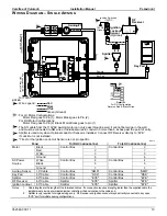
For Single Awning installations: refer to wiring diagram on page 8.
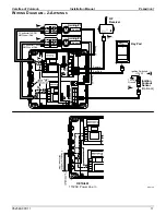
For 2- Awning installations: refer to wiring diagram on page 11.
For 4-Awning installations: refer to wiring diagram on page 13.
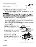
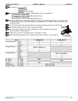
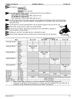
1.
Locate the mounting location of the control
box(es). Each box requires a flat area
approximately 6 1/2" x 6 1/2" with a clearance depth
of 2 3/8".
For 4 awning installations:
A 60" jumper cable is used
between the two control boxes. This allows
approximately 55" of cable between the boxes.
Position the boxes to allow the jumper to be connected
and routed with some slack in the cable.
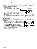
2. Remove the lid. Attach the box to the mounting surface
using a minimum of two (2) #8 x 3/4 screws each. The
screws must be mounted in opposite corners.
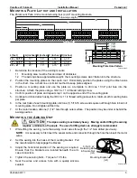
3. Route a 2-conductor 14AWG NM wire with ground from the AC power source to the box. It is
recommended that the installer provide a dedicated AC circuit that is protected by an appropriate sized
fuse/circuit breaker. Each patio awning draws a maximum of 3 amps.
NOTE:
Each board must have a 110VAC supply. The diagram shows a separate power source for each
box; each power source is spliced with wire nuts to power both boards in a box.
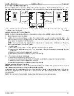
4. Connect the wires to the control box circuit boards as shown in the wiring diagram (Detail A).
5. Route the motor wires from awning #1 to controller #1 (motor#1); attach the wires to the terminals as shown.
NOTE: For LH motor configurations:
RED WIRE
goes to terminal (1);
BLACK WIRE
goes to terminal (2).
For RH motor configurations:
RED WIRE
goes to terminal (2);
BLACK WIRE
goes to terminal (1).
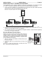
6. Attach the RJ11 cable from the sensor of awning #1 to the "AMD" receptacle of controller #1.
7. Repeat step 5 and 6 for the other awnings.
8. After testing connections, use Loctite 29005 or equivalent to secure screws in terminal block.
9. Attach the remaining RJ11 cables as shown in the wiring diagram. Use the slot cutouts in the box to
route the phone cables.
NOTE:
The key pad and RF receiver only attach to controller #1.
#8 x 3/4 Screw (2)
RTA019c
6 1/2”
(typ)
2 3/8”


