

By CARDIN ELETTRONICA spa
Via Raffaello, 36
CODE
FA0019
SERIES
SL
MODEL
1524
DATE
22-07-2003
31020 San Vendemiano (TV) Italy
Tel:
Fax:
email (Italian): Sales.office.[email protected]
email (Europe):
Sales.[email protected]
Http:
Questo prodotto è stato testato e collaudato nei laboratori della casa
costruttrice, la quale ne ha verificato la perfetta corrispondenza delle
caratteristiche con quelle richieste dalla normativa vigente.
This product has been tried and tested in the manufacturer's laboratory
who have verified that the product conforms in every aspect to the
safety standards in force.
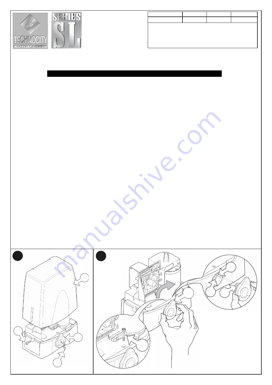
Vervangen manuele ontgrendeling SL1524
Replacing the manual release unit SL1524
ITALIANO
ENGLISH
Procedure
1) Schakel de stroom uit,en blokkeer de ontgrendeling met
De bijgeleverde veiligheids sleutel
“A” (fig.1)
.
2)
Maak beide schroeven
“D” (fig.1)
los , midden van de
motor en verwijder de motorhoed “
C
”.
3) Schroef de blokkeer schoef
“E” (fig. 2a)los en verwijder
Deze.
4)
Draai de ontgrendeling
“F” (fig. 2) 30°
in de richting van ,
de klok met betrekking van de standaard positie.
5)
Trek de volledige ontgrendeling
(fig. 2b)
naar u toe en
controleer de positie van de ontgrendel pen
“I” (fig. 2b)
.
6)
Plaats een nieuwe ontgrendeling
(fig. 2b)
, en zie dat de
voet
“H”
overeen komt met de voorziene uitsparing
“G”
in
de motor .Bij plaatsing van de nieuwe ontgrendeling denk
eraan deze ook
30°
te draaien in richting van de
ontgrendel positie
(fig. 2b)
.
7) Duw de ontgrendeling voorzichtig in zijn behuizing
(fig. 2b)
.
8)
Draai nu de ontgrendeling 30° tegen de klok tot deze
volledig vertikaal staat
“B” (fig. 1)
de ontgrendeling moet
hiervoor met de sleutel vergrendeld zijn . (indien nodig mag
U hierbij gebruik maken van een rubberen hamer ).
9)
Als de ontgrendeling mooi vertikaal staat zal zal het gat voor de
blokkeer schroef mooi overeen komen
en u toelaten deze
zonder veel moeite terug te plaatsen .
10) Plaats de blokkeer schoef terug
“E” (fig. 2a)
e tot deze
zijn eindpunt bereikt ,draai dan een kwart terug los tot u
voeld dat de ontgrendeling soepel werkt.
11) Plaats de motor kap terug en sluit de stroom terug aan .
Replacement procedure
1) Switch off the power at the mains and block the rotation of
the manual release knob using the security key
“A” (fig.1)
.
2)
Loosen the two screws
“D” (fig.1)
located laterally on the
motor and remove the cover
“C”
.
3)
Unscrew and remove the release mechanism blocking
screw
“E” (fig. 2a).
4)
Rotate the knob
“F” (fig. 2) 30°
clockwise with respect to
the default position.
5)
Extract the release mechanism unit
(fig. 2b)
carefully and
check the correct position of the pin
“I” (fig. 2b)
.
6)
Insert the new release mechanism unit
(fig. 2b)
, and allow
the seat
“H”
to line up with the reference tab
“G”
on the
release unit collar.
When inserting the unit remember to first turn it
30°
with
respect to the default position
(fig. 2b)
.
7) Press the release unit carefully into its seat
(fig. 2b)
.
8)
Rotate knob anticlockwise (without touching the release
key) to move it back to the default position (vertical position)
“B” (fig. 1)
force down slightly to make sure that the unit fits
snugly into its seat (if necessary tap the unit lightly useing
a rubber mallet).
9)
The exact vertical position will line up the lock screw hole
with the relative hole on the release unit and allow you to
insert and fasten down the release mechanism blocking
screw easily.
10) Insert the release mechanism blocking screw
“E” (fig. 2a)
and fasten down until it has reached the hole on the release
unit; do not overtighten!
11) Replace the cover and switch on the power at the mains.
1
2
C
30
°
F
H
2b
I
G
D
B
2a
E
A


