background image


[email protected] 

docs.carbide3d.com


10/02/2020 

Version 1.0


29 

Install the Proximity Switch Mounts 

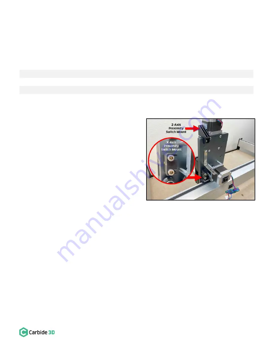
Install the X- and Z-Axis Proximity Switch Mounts 

Required Components: 

Item 

Description 

Qty 

X-Axis Proximity Switch Mount 

M5 × 25mm Socket Head Cap Screw 

Z-Axis Proximity Switch Mount 

M4 × 6mm Button Head Cap Screw 


1.


Install the X-Axis proximity switch mount to the 
back of the HDZ. See 

Fig. 28 

and 

Fig. 28 inset

a.


Align the mounting slots with the two M5 
screw holes on the Y2-side of the X-motor. 

b.


The two gold-colored threaded inserts on 
the mount face out (away from X-motor).  

c.


Use a 4mm hex key and two (2) 
M5

×

25mm SHCS to secure. 

d.


Before fully tightening the screws, slide 
the mount toward the X-motor far as it 
will go. 

2.


Install the Z-Axis proximity switch mount to the 
back of the HDZ. See 

Fig. 28

.  

a.


Align the mount with the M4 screw hole 
at the very top of the HDZ. 

b.


Use a 2.5mm hex key and one (1) M4

×

6mm BHCS to secure the mount at the top of the HDZ.  


Figure 28


Summary of Contents for Shapeoko Proximity Switch Kit

Page 1: ...support carbide3d com docs carbide3d com 10 02 2020 Version 1 0 1 Proximity Switch Upgrade ASSEMBLY GUIDE...

Page 2: ...support carbide3d com docs carbide3d com 10 02 2020 Version 1 0 2...

Page 3: ...Disassembly 8 Prep and Re Install the Drag Chain 11 Install the Proximity Switches and Mounts 15 Connect and Cleanup Cables 20 HDZ Proximity Switch Upgrade 24 Prior to Assembly Installation 24 Invento...

Page 4: ...l Instructions and Call Outs There are minor differences in the installation procedures between Shapeoko 3 XL and XXL We ve added special notes to guide you whenever these differences require alternat...

Page 5: ...you have the BitSetter checkbox checked go ahead and uncheck it You will need to re calibrate the BitSetter after successful homing with your new proximity switches See page 41 for instructions Gather...

Page 6: ...support carbide3d com docs carbide3d com 10 02 2020 Version 1 0 6 Inventory Figure 1...

Page 7: ...mm Socket Head Cap Screw 2 F M3 18mm Socket Head Cap Screw 2 Y Axis Proximity Switch Mount Baggie G Y Axis Proximity Switch Mount 1 H M5 35mm Socket Head Cap Screw 2 I M3 18mm Socket Head Cap Screw 2...

Page 8: ...r motor lead cables AND the X Y1 Y2 and Z stepper motor extension cables 5 Disconnect all cables a Remove the Carbide Motion board enclosure cover b Disconnect the X Y1 Y2 and Z motor leads from their...

Page 9: ...ches from their mounting plates b Use a 3mm hex key to remove the four 4 M5 10mm BHCS securing the four 4 1 inch standoffs and the head bracket c Set the X Axis head bracket aside for re installation...

Page 10: ...n from the rails and lay it on the baseframe as shown in Fig 4 a Pry the tail ends of the drag chain from the VHB tape securing them to the rails b Lay the drag chain on the baseframe for proximity sw...

Page 11: ...baseframe as shown in Fig 6 with the chain s clip on panels facing up Only one side of the chain will open be sure this side is facing up b Use a hex key or screwdriver as a lever to pry open one side...

Page 12: ...into the drag chain See Fig 7 a Insert the X and Z Axis proximity switch cables through both the Y Axis and X Axis portions of the drag chain b Insert the Y Axis proximity switch cable through the Y...

Page 13: ...the PEM nut toward the Y2 side and overhanging the back of the rail Get the PEM nut as close to the rail as you can without obstructing it e Press the plate to the rail for 30 seconds 2 Attach one 1...

Page 14: ...e drag chains so that the tail of the Y Axis drag chain will curl under and the head of the X Axis drag chain will curl up 3 Secure the drag chain to the rails but leave the X Axis drag chain head dis...

Page 15: ...to the back of the X Z carriage See Fig 12 a Position the proximity switch mount with the two gold colored threaded inserts facing out away from X motor and the screw head recesses at the end of each...

Page 16: ...5 35mm SHCS to secure Install the Z Axis Proximity Switch and Mount Required Components Item Description Qty C Z Axis Proximity Switch 2675mm XXL 2350mm XL and 610mm Shapeoko 3 1 L M3 18mm Socket Head...

Page 17: ...bracket Re Installation of the X Axis Head Bracket Required Components Item Description Qty N A X Axis Drag Chain Head Bracket 1 R M3 8mm Flat Head Screw Replacement 2 S M3 Nyloc Nut Replacement 2 1...

Page 18: ...t installed on the rear of the X Z carriage See Fig 17 a Locate the X Axis proximity switch exiting the drag chain at the X Axis head bracket b Position the proximity switch with the red LED facing th...

Page 19: ...e mount on the outside of the Y2 carriage See Fig 18 a Locate the Y Axis proximity switch exiting the drag chain at the Y Axis head bracket b Position the proximity switch with the red LED facing out...

Page 20: ...es to the Carbide Motion Board Required Components Item Description Qty M PCB Riser Board 1 Shapeoko XXL and XL Instructions 1 Plug the PCB riser board into the Carbide Motion board See Fig 19 a Plug...

Page 21: ...Motion board 2 Plug the proximity switch cables and stepper motor extension cables into the Carbide Motion board See Fig 20 a Plug each of the proximity switch cables Z Y and X into the PCB riser boa...

Page 22: ...les one at a time into the cutout at the top of the Y1 carriage plate b Use two 2 cable ties one on each side of the cutout to secure the cables in place 2 Secure the cables at the rear of the X Z car...

Page 23: ...he cables along the rear of the X rail See Fig 23 a Secure the loose cables to the four self adhesive cable tie mounts already attached to the back of the X rail Post Installation Instructions Please...

Page 24: ...have the BitSetter checkbox checked go ahead and uncheck it You will need to re calibrate the BitSetter after successful homing with your new proximity switches See page 41 for instructions Gather th...

Page 25: ...support carbide3d com docs carbide3d com 10 02 2020 Version 1 0 25 Inventory Figure 24...

Page 26: ...Socket Head Cap Screw 2 F M3 18mm Socket Head Cap Screw 2 Y Axis Proximity Switch Mount Baggie G Y Axis Proximity Switch Mount 1 H M5 35mm Socket Head Cap Screw 2 I M3 18mm Socket Head Cap Screw 2 Z...

Page 27: ...nd Z stepper motor lead cables AND the gray X Y1 Y2 and Z stepper motor extension cables 5 Disconnect all cables a Remove the Carbide Motion board enclosure cover b Disconnect the X Y1 Y2 and Z motor...

Page 28: ...e two 2 M5 35mm SHCS and two 2 1 inch spacers 4 Disconnect the drag chain from the X Axis head bracket on the rear of the HDZ a Use a 2mm hex key and needle nose pliers to remove the two 2 M3 6mm FHS...

Page 29: ...the HDZ See Fig 28 and Fig 28 inset a Align the mounting slots with the two M5 screw holes on the Y2 side of the X motor b The two gold colored threaded inserts on the mount face out away from X moto...

Page 30: ...Qty G Y Axis Proximity Switch Mount 1 H M5 35mm Socket Head Cap Screw 2 1 Install the Y Axis proximity switch mount to the outside of the Y2 carriage See Fig 29 a Align the mount with the two M5 holes...

Page 31: ...the baseframe as shown in Fig 31 with the chain s clip on panels facing up Only one side of the chain will open be sure this side is facing up b Use a hex key or screwdriver as a lever to pry open on...

Page 32: ...into the drag chain See Fig 32 a Insert the X and Z Axis proximity switch cables through both the Y Axis and X Axis portions of the drag chain b Insert the Y Axis proximity switch cable through the Y...

Page 33: ...arks with the PEM nut toward the Y2 side and overhanging the back of the rail Get the PEM nut as close to the rail as you can without obstructing it e Press the plate to the rail for 30 seconds 2 Atta...

Page 34: ...ead of the X Axis drag chain will curl up 3 Secure the drag chain to the rails See Fig 36 a Secure the Y Axis drag chain head to the head bracket on the outside of the Y1 carriage i Use a 2mm hex key...

Page 35: ...acket b Position the proximity switch with the red LED facing the Y2 carriage and the target pointing down c Align the proximity switch s mounting slots with the two threaded inserts on the face of th...

Page 36: ...the drag chain at the Y Axis head bracket b Position the proximity switch with the red LED facing out and the target pointing to the rear of the machine c Align the switch s two mounting slots with t...

Page 37: ...rly Connect Cables to the Carbide Motion Board Required Components Item Description Qty M PCB Riser Board 1 Shapeoko XXL and XL Instructions 1 Plug the PCB riser board into the Carbide Motion board Se...

Page 38: ...ard into the 2 8 open bank of pins in the bottom left of the Carbide Motion board 2 Plug the proximity switch cables and stepper motor extension cables into the Carbide Motion board See Fig 40 a Plug...

Page 39: ...a Tuck all seven cables one at a time into the cutout at the top of the Y1 carriage plate b Use two 2 cable ties one on each side of the cutout to secure the cables in place 2 Secure the cables at the...

Page 40: ...s Along the X Rail Cable Cleanup Required Components Item Description Qty T 4 Cable Ties Several 1 Tidy up the cables along the rear of the X rail See Fig 43 a Secure the loose cables to the four self...

Page 41: ...so check to see that a blue LED lights up on the Carbide Motion board A detailed video on proximity switch testing is available here https youtu be Zf8NPmxrEDs Home Your Shapeoko Once all switches hav...

Page 42: ...ick DONE c From the Jog screen use the arrows on the screen or the arrows on your keyboard to jog the gantry so the spindle is directly above the BitSetter Once you have the spindle positioned directl...

Reviews: