S T E P 5
S T E P 5 – X / Z A s s e m b l y
36
docs.carbide3d.com
37
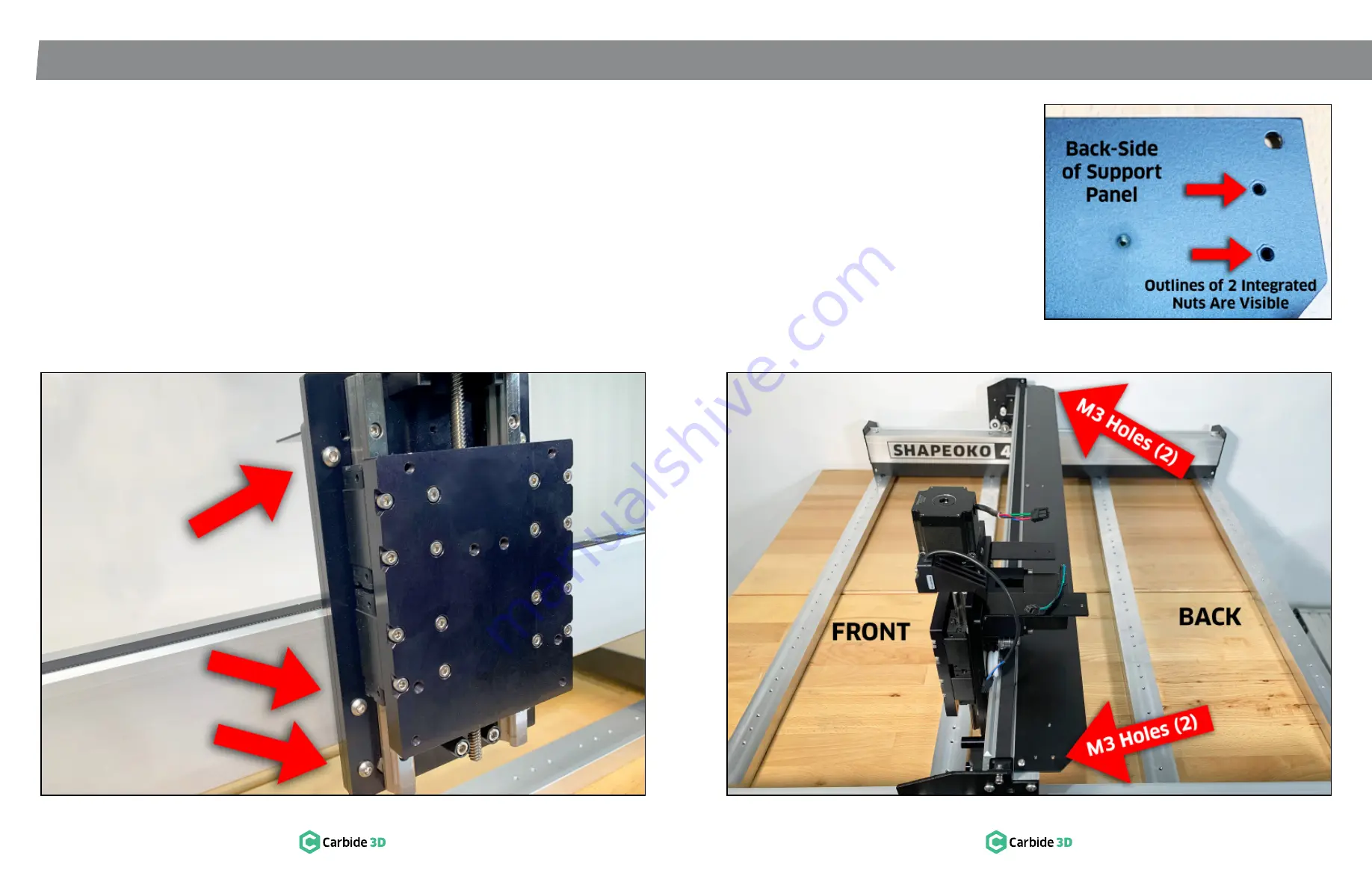
Figure 5-11
Figure 5-12
5.9 Install X/Z Assembly
1. Slide the Z-Axis plate on the front of the
X/Z assembly until it is centered on the linear
rails and all six M6 holes on the front of the
assembly are accessible.
See
Fig. 5-11
.
2. Position the X/Z assembly over the FRONT of
the X/Z carrier plate.
See
Fig. 5-11
.
a. Z-Axis plate facing front.
b. Z-Axis stepper motor on top.
3. Use a 4mm hex key and six (6) M6×12mm
BHCS to secure the X/Z assembly to the M6
holes on the carrier plate. Fully tighten.
5.10 Install X‑Axis Drag
Chain Support Panel
1. Identify the back-side of the X-Axis drag chain
support panel.
See
Fig. 5-13
.
a. The set of two M3 integrated nuts, spaced
about 1″ apart and located at each end of
the panel, are pressed into the BACK-SIDE
of the panel. Look for the outline of these
four nuts on the back-side.
IMPORTANT:
Be sure to correctly identify the
front and back of the support panel. The panel will
only work properly one way.
2. Use a 2mm hex key and three (3) M3×6mm
BHCS to secure three cable tie mounts to
three right-side up nuts on the BACK-SIDE of
the support panel.
3. Position the support panel RIGHT-SIDE UP
across the top-back of the gantry.
a. Tapered corners to the back.
b. Five M5 holes to the front.
c. Two integrated M3 nuts at each end.
4. Use a 2.5mm hex key and five (5) M4×6mm
BHCS to secure the support panel to the
gantry.
See
Fig. 5-12
.
Figure 5-13


